

Date:2026-08-11 Click:183
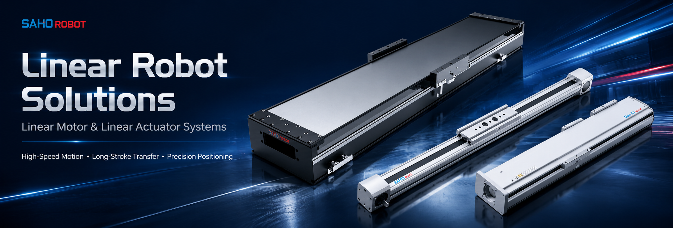
A linear robot does not need the same drive technology on every axis. In a machine that combines long transfer, motion-sensitive inspection, and vertical tooling, those jobs create different requirements. The base axis may be selected for travel and cycle time, the process axis for motion quality, and the vertical axis for thrust and safe stopping.
This guide focuses on one specific architecture: using a TA Series belt-driven module for long transfer, an NK Series direct-drive stage where the process occurs during movement, and an SDM Series ball screw actuator for controlled local or vertical positioning. It explains when all three are justified, how one axis changes the load seen by the next, and what data must be checked before choosing model sizes.
If the project only needs belt and screw axes, see the existing multi-axis belt and screw system guide. For a general comparison of the three drive technologies as individual axes, use the linear axis selection guide. The decision here is narrower: how to combine different drive families in one coordinated machine without over-sizing every direction.
| Core rule: use three drive families only when the machine has three genuinely different motion jobs. A stop-and-capture camera does not automatically need direct drive, and a simple transfer-and-lift unit may need only TA and SDM. |
When a Mixed-Drive Linear Robot Is Actually Justified
Begin with the process timeline rather than the product catalog. Mark where the tool moves, where production work occurs, whether a sensor collects data during travel, and which axis must support a load against gravity. The answer determines whether a third drive family creates measurable value or only adds cost and control complexity.
| Motion job | Starting family | Evidence required |
| Long station-to-station transfer | TA belt drive | Useful stroke, full moving assembly, move time, acceleration, settling and cable drag |
| Continuous scan or process during travel | NK direct drive | Velocity quality, sampling method, thrust profile, thermal duty, feedback and frame stiffness |
| Vertical lift or controlled local approach | SDM ball screw | Thrust, screw lead, stroke, speed, duty cycle, brake and drop-prevention method |
The inspection method is an important dividing line. If a camera or laser measures continuously while the stage moves, the motion profile directly affects data spacing and process quality. NK becomes a relevant starting point. If the axis stops before every capture and the settling target is moderate, an SDM screw axis may complete the task without adding a direct-drive stage.
Calculate the Axis Stack from the Tool Back to the Base
Multi-axis sizing must follow the physical load path. Start with the end effector and the axis that carries it. Then add that complete assembly to the next supporting axis. Continue until the base axis includes every component that moves with its carriage.
| Axis layer | Include in moving mass | Do not overlook |
| Tool or Z assembly | Product, gripper, camera, lighting, process head, moving plate and local brackets | Hoses, connectors, protective parts and tool offset |
| Process or cross axis | Complete tool/Z assembly plus the cross-axis moving hardware | Cable carrier force, unsupported bracket length and moment load |
| TA base axis | Complete upper-axis assembly, bridge parts carried by the carriage, services and payload | Structure mass that moves even when the product is light |
A useful engineering check is to write one mass equation for each axis. For example, the base-axis moving mass equals the complete process-axis assembly, the complete Z assembly, the tool and product, moving bridge hardware, and the portion of cables or hoses carried by that base carriage. Do not count only the workpiece.
Record center-of-gravity offsets as well. Moment load follows force multiplied by offset distance, so a light inspection head on a long bracket can be harder to control than a heavier centered load. Check the actual carriage and guide limits for the selected model and mounting orientation.
One Product System, Three Defined Axis Roles
TA, NK and SDM should be treated as a coordinated product system, not three interchangeable recommendations. Each family enters the architecture for a different reason. Model numbers shown in the images are product references; final model selection must follow the current series data, required stroke, moving load, motion profile and installation condition.
TA Series: the long transfer layer
The TA Series is SAHO's high-speed silent belt-driven linear actuator family. In this architecture, TA is reviewed for the base or long horizontal transfer direction. Selection must use total moving mass, useful stroke, acceleration, move time, settling requirement, load offset, cable force and mounting support rather than stroke alone.
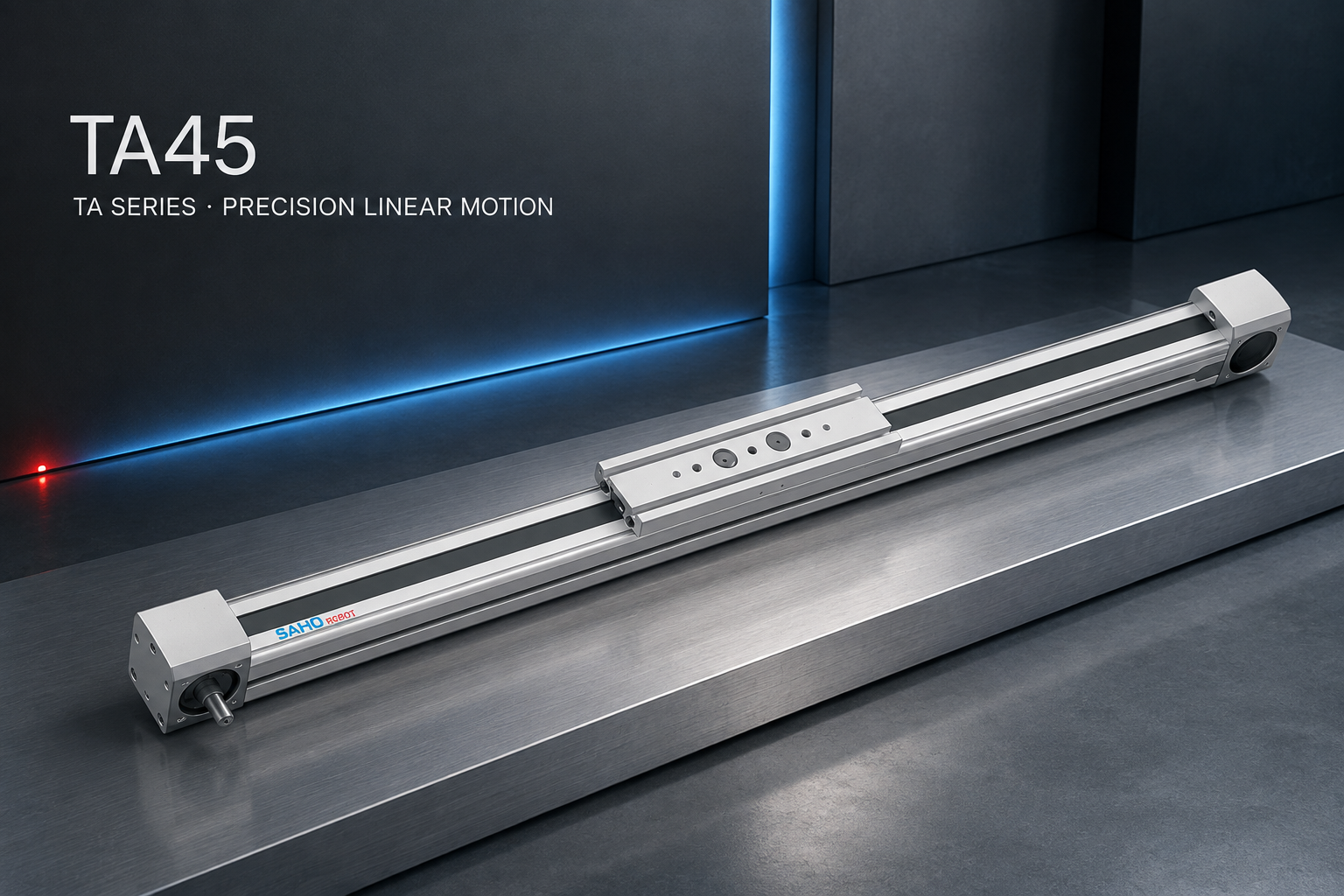
TA45 is shown as a TA Series reference. Confirm the selected TA model against the complete upper-axis assembly and required motion profile.
NK Series: the motion-sensitive process layer
The NK Series is a steel-belt-protected linear motor stage. The steel belt is a protective cover; it is not a timing-belt transmission. NK is relevant when the process benefits from direct drive, such as continuous camera or laser scanning, frequent short moves, demanding response, or a tight move-and-settle target.
Size the chosen NK model by continuous and peak thrust requirements, complete moving mass, acceleration, speed profile, duty cycle, thermal condition, feedback system, cable drag and base stiffness. A high-performance stage cannot correct a flexible camera bracket, unstable bridge or unsuitable controller tuning.
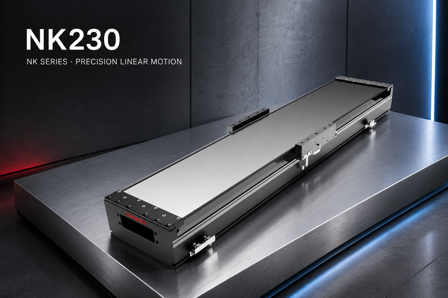
NK230 is shown as an NK Series reference. Confirm thrust, travel, speed profile, feedback and thermal duty for the real process.
SDM Series: the controlled local or vertical layer
The SDM Series is a ball screw linear actuator family for stable positioning, thrust support and general automation. In a mixed-drive robot, SDM can handle tool height, camera adjustment, probe approach, fixture positioning or a vertical working direction when its model and safety structure are correctly selected.
Confirm screw lead, usable stroke, required thrust, speed, duty cycle, repeatability target, lubrication access and mounting orientation. A vertical axis also needs a motor brake or other holding method, power-loss behavior, mechanical drop prevention where required, safe clearance and a documented recovery sequence.
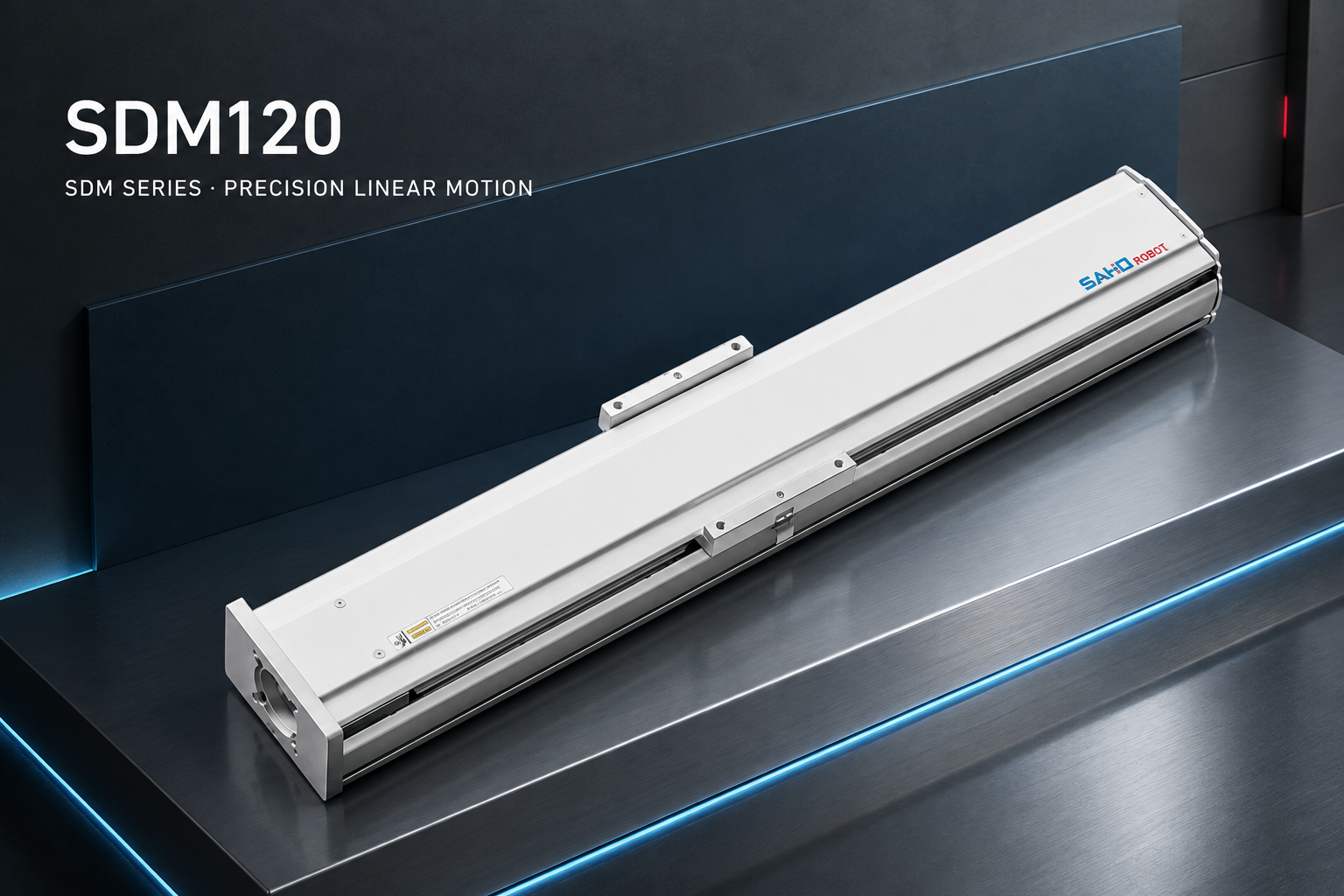
SDM120 is shown as an SDM Series reference. Confirm screw lead, load, stroke, brake and safe-stop requirements for vertical use.
Three Configurations That Keep the Product Logic Clear
TA X + SDM Z: transfer and lift without a scan axis
Use this two-family structure for loading, unloading, tray transfer and pick-and-place when the tool does not perform a motion-sensitive process during travel. TA carries the complete SDM assembly, end effector, product and moving services. SDM handles lift or local approach with the required vertical safety measures. Adding NK here would need a clear cycle-time or process-quality reason.
TA X + NK process axis + SDM Z: full mixed-drive inspection platform
Use TA to move the inspection assembly between work zones, NK for the path where a camera or laser collects data during motion, and SDM for focus height, sensor distance, probe approach or fixture adjustment. The TA axis must carry the complete NK and SDM structure. NK sizing must include the moving sensor assembly and cable force, while SDM vertical sizing must include the tool and its holding risk.
Paired TA base axes + NK process axis + SDM Z: wide gantry
A wide bridge may require two base axes when one-sided support cannot control racking and bridge deflection. The paired TA axes, bridge, controller and homing system must be engineered as one synchronized base. NK can then provide the motion-sensitive local path, while SDM controls the vertical tool direction. This layout needs verified mechanical parallelism, bridge stiffness, synchronization behavior and safe stopping before model selection.
Control, Frame and Safety Checks for Mixed Drives
Belt, direct-drive and ball screw axes should not receive one copied motion profile. Their acceleration limits, settling behavior, feedback, thermal condition and maintenance needs differ. The controller must support the selected motors, drives, feedback devices, brake signals, limits, home sensors and synchronization method.
Frame response: NK acceleration can excite a flexible bridge or bracket. Validate the complete structure, not only the stage repeatability.
Homing order: define a safe sequence for the actual machine. A vertical tool may need to retract before the base or process axis moves.
Paired-axis behavior: a dual-base gantry needs mechanical alignment, synchronized homing, fault handling and a strategy that prevents racking.
Cable influence: cable-chain mass and changing drag force affect TA motor demand and can disturb an NK scan path.
Power-loss state: document what every axis does after an emergency stop, drive alarm, feedback fault or power interruption, especially when SDM is vertical.
Parameters to Confirm Before Choosing TA, NK or SDM Models
Do not transfer a headline speed, thrust or repeatability value from one model to the whole series. Available performance changes with model size, stroke, motor or drive configuration, load, acceleration, duty cycle, feedback and installation. Use the current product data and ask SAHO to confirm the final operating point.
| Family | Parameters that control selection |
| TA | Useful stroke, total moving mass, acceleration, move time, repeatability target, load offset, settling, cable drag, support and motor position |
| NK | Continuous and peak thrust, moving mass, speed profile, acceleration, duty cycle, thermal condition, feedback, cable force, base stiffness and motion-quality target |
| SDM | Screw lead, usable stroke, thrust, speed, repeatability target, duty cycle, vertical load, brake, lubrication, mounting orientation and safe-stop requirement |
Information to Send for a Mixed-Drive Selection Review
Prepare one row of project data for every axis and attach a sketch that shows the axis order. Identify which components move with TA, which components move with NK, and which load SDM supports. The sketch should also show motor sides, travel directions, home positions, cable routes, work zones and available installation space.
| Project input | What to provide for each axis |
| Motion | Useful stroke, move distance, target move time, velocity profile, acceleration, dwell, settling and cycles per minute |
| Load | Complete moving mass, component list, product and tool mass, center-of-gravity offsets, process force and cable drag |
| Process | Whether work occurs during motion or after stopping, plus repeatability, path, settling or sampling requirements |
| Installation | Axis order, horizontal or vertical mounting, base and bridge material, motor direction, cable space and service access |
| Environment and safety | Temperature, contamination, duty cycle, maintenance plan, brake, guarding, emergency stop and expected power-loss behavior |
FAQ
Does a three-axis robot always need TA, NK and SDM?
No. Use NK only when a motion-sensitive process or demanding dynamic target justifies direct drive. A transfer-and-lift machine may need only TA and SDM, while a scan platform without vertical movement may use TA and NK.
Can NK replace TA as the main long axis?
It can be reviewed when the long axis itself controls scan quality, response or settling. The decision must compare required thrust, thermal duty, travel, moving mass, frame stiffness, feedback and project cost. Direct drive should not replace a practical transfer axis without a process reason.
What most often causes the TA base axis to be undersized?
The calculation uses product weight but omits the complete NK or SDM assembly, bridge hardware, mounting plates, gripper, sensor brackets and moving cable system. Load offset, acceleration and changing cable drag can then create more demand than the nominal payload suggests.
Is an SDM screw axis automatically safe for vertical use?
No. The selected model must be checked for vertical load, screw lead, speed, duty cycle and motor brake. The machine also needs suitable holding, drop-prevention, guarding, clearance and safe-stop logic based on its risk assessment.
Final Selection Direction
Build the motion architecture before choosing model sizes. Use TA for the justified transfer role, NK for a process that gains measurable value from direct drive, and SDM for controlled local or vertical motion. Size from the tool back to the base, keep each axis parameter set separate, and verify the controller, frame, cables and safety behavior as one machine.
Send the Complete Axis Stack for ReviewSend SAHO a layout sketch and one data row for every axis: axis role, stroke, complete moving mass, center-of-gravity offset, speed profile, acceleration, process timing, repeatability or motion-quality target, installation direction, duty cycle, environment, cable path and power-loss requirement. SAHO can then review whether the machine needs TA, NK and SDM together and identify the appropriate model direction without relying on assumed parameters. |







-
-
 English
 -
 Français
 -
 Deutschland
 -
 Italia
 -
 Polska
 -
 España
 -
 Русский язык
 -
 日語
日語 -
 한국
한국 -
 Türkiye
 -
 português
 -
 بالعربيةês
 -
 Tiếng Việt
 -
 คนไทย
คนไทย -
 简体中文
简体中文 -
繁體中文
-