

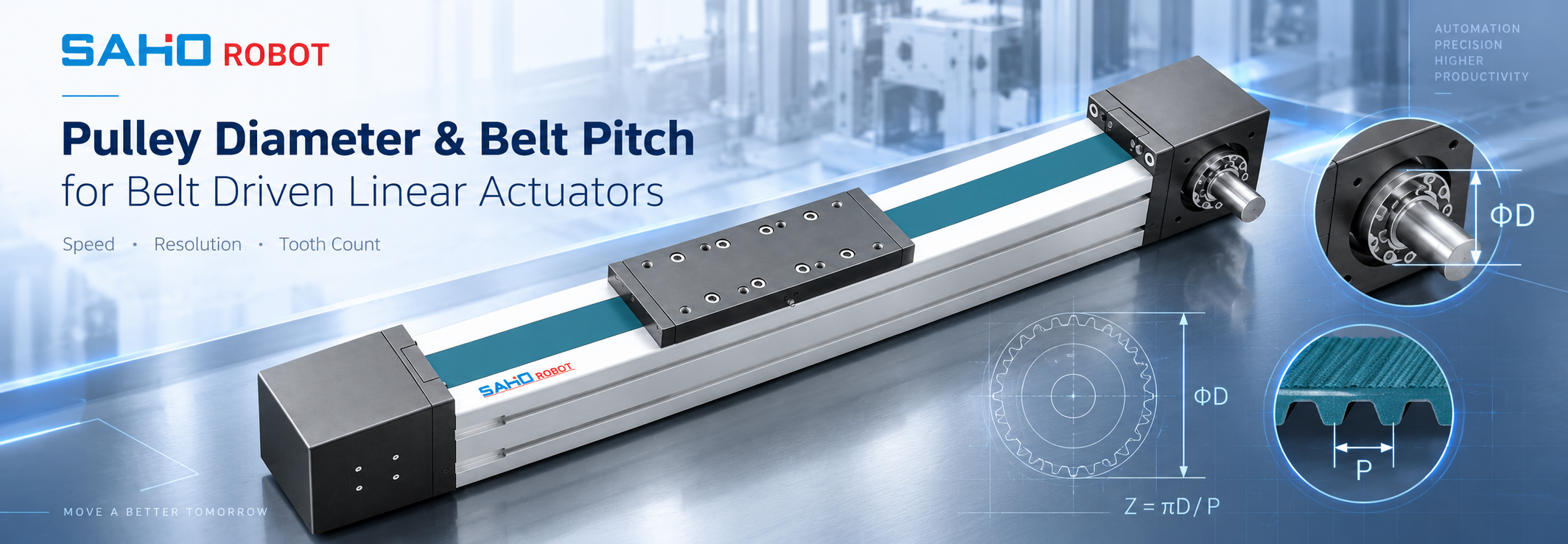
Pulley diameter and belt pitch should be selected as one matched transmission, not as separate components. For a belt-driven axis, the belt actuator pulley diameter follows from belt pitch and pulley tooth count, and that geometry sets the belt travel produced by each pulley revolution. Pulley rpm then determines linear speed. A workable combination must also provide suitable tooth engagement and wrap, remain within the belt supplier's minimum-pulley guidance, and match the motor's torque and inertia requirements. The practical sequence is to select a compatible belt profile and pitch, choose an available tooth count, calculate pitch diameter and speed, then verify engagement, bending, motor demand, pulley width, and supplier limits.
Selection rule: do not choose a pulley only because it produces the required speed. The pulley must satisfy the speed calculation, belt geometry, motor-side torque and inertia check, and the selected belt manufacturer's limits at the same time.
Relate Belt Pitch, Pulley Tooth Count, and Pitch Diameter First
The useful diameter for a synchronous belt calculation is the pitch diameter, not the outside diameter measured across the pulley teeth. The pitch diameter describes the theoretical circle followed by the belt pitch line and therefore controls the relationship between pulley rotation and belt travel.
Pitch diameter relationship
Dp = (z × p) / π
Here, Dp is pitch diameter, z is pulley tooth count, and p is belt pitch. At a fixed pitch, adding pulley teeth increases timing pulley diameter. At a fixed tooth count, selecting a larger pitch also increases diameter.
The same geometry gives a practical linear-axis value:
Belt travel per pulley revolution = z × p
An illustrative 20-tooth pulley with a 5 mm pitch therefore produces 100 mm of pitch-line travel per revolution. A 30-tooth pulley with the same pitch produces 150 mm. These values demonstrate the geometry only; they are not SAHO JTG specifications or approved pulley combinations.
Belt pitch selection also means selecting a compatible tooth profile, belt width, and pulley geometry. Start with the belt family and manufacturer's load-rating method: check peak belt force, acceleration and duty cycle against the available pitch and width options, then check the minimum permitted pulley size, tooth engagement and installation space. A larger pitch is not automatically the better choice, and two belts with the same nominal pitch are not necessarily interchangeable if their tooth profiles differ. Before applying a calculated combination to an actual module, compare it with the current drawings and approved transmission configuration for the JTG belt driven linear actuator. For JTG variants or proposed substitutions not confirmed in current technical data, use engineering confirmation required rather than assuming that a generic pulley can be substituted.
Convert Timing Pulley RPM into Linear Speed
Once pitch and tooth count are known, rotational speed can be converted directly into belt linear speed. This is the central relationship behind timing pulley rpm to linear speed.
Linear speed from tooth count and belt pitch
v = (z × p × n) / 60
In this form, v is linear speed in mm/s when belt pitch p is in millimetres and pulley speed n is in rpm. If target linear speed is already known, rearrange the equation:
n = (60 × v) / (z × p)
Using the illustrative 20-tooth, 5 mm pitch combination, the pulley produces 100 mm per revolution. At 1,500 rpm, theoretical belt speed is 2,500 mm/s, or 2.5 m/s. This is an engineering example, not a stated JTG operating limit.
The reverse calculation is useful during motor matching. If target linear speed requires excessive pulley rpm, increasing tooth count may reduce the rotational-speed requirement. That change also increases pitch radius, however, so torque demand and reflected inertia must be checked before accepting the larger pulley.
These speed relationships assume that the pulley drives the belt directly, with pulley rpm used in the equations. Where a gearbox is present, convert motor rpm to pulley rpm using the actual transmission ratio before applying them.
If pulley selection is part of a wider Cartesian or gantry-axis decision, the related guide to belt modules for gantry systems provides the machine-level context for stroke, moving structure, acceleration, and motor matching.
Check Tooth Engagement, Wrap Angle, and Minimum Pulley Diameter
A speed calculation can be correct while the belt transmission is still unsuitable. The belt must wrap far enough around the pulley to provide appropriate tooth engagement, and the pulley must not bend the selected belt more sharply than its supplier permits.
Approximate geometrical teeth in mesh
Engaged teeth ≈ z × wrap angle / 360°
With an illustrative 180° wrap, a 20-tooth pulley has about 10 teeth geometrically in mesh, while a 30-tooth pulley has about 15. This does not create a universal acceptance limit. Required tooth engagement depends on the belt profile, pulley arrangement, belt width, transmitted force, and the supplier's rating method.
Wrap also changes when pulley diameters differ or packaging constraints alter the belt path. The smaller pulley often deserves the closest review because it combines tighter belt bending with fewer teeth available for engagement.
There is no universal minimum pulley diameter. Depending on the belt family, supplier guidance may be expressed as minimum tooth count, minimum pitch diameter, minimum bending radius, or separate requirements for reverse bending and backside idlers. Use the data for the exact belt being selected.
Before accepting a small pulley, confirm tooth profile compatibility, minimum tooth count or diameter, allowable belt and pulley speed, required engagement, belt and pulley width, flange arrangement, and any supplier correction factors that apply to the transmission.
Balance Pulley Diameter Against Motor Torque, Inertia, and Belt Bending
Increasing pulley diameter is not a free way to obtain more belt driven linear actuator speed. Pitch radius also changes the mechanical conversion between motor torque and linear force.
First-pass torque relationship
T ≈ F × rp
Here, T is pulley torque, F is tangential belt force, and rp is pitch radius. Use F in newtons (N) and rp in metres (m) to obtain T in newton-metres (N·m); convert a pitch radius calculated in millimetres before substitution. This ideal relationship does not include transmission losses, but it shows the tradeoff clearly: if pitch radius increases by 50%, the ideal torque required for the same linear force also increases by 50%.
For a pulley driven directly by the motor, the moving mass contributes inertia at the motor shaft. A simplified relationship is:
Jreflected = m × rp²
With m in kilograms (kg) and rp in metres (m), Jreflected is expressed in kg·m². A 1.5× increase in pitch radius therefore makes this translated-mass contribution 2.25× larger. If a gearbox is present, reflect this load inertia to the motor shaft using the actual gearbox ratio; the direct-drive expression cannot be applied unchanged at the motor. Actual motor sizing must also consider pulley and coupling inertia, the complete moving mass, acceleration, duty profile, and applicable mechanical losses.
The engineering tradeoff: a larger pulley gives more travel per revolution, reduces rpm for a given linear speed, and provides a larger belt bending radius. A smaller pulley provides less travel per revolution and more ideal linear force per unit torque, but bending, rpm, tooth engagement, and minimum-pulley restrictions can become more demanding.
Worked Comparison: Two Pulley Choices for the Same Belt Pitch
The following comparison uses two theoretical pulleys with the same 5 mm belt pitch. It shows how to choose pulley diameter for a belt actuator by checking several consequences together. The values are illustrative and are not JTG product data or approved configurations.
| Comparison point | 20 teeth | 30 teeth | Selection effect |
|---|---|---|---|
| Pitch diameter | 31.83 mm | 47.75 mm | 30-tooth radius is 1.5× larger. |
| Travel per revolution | 100 mm | 150 mm | Larger pulley moves farther per revolution. |
| Speed at 1,500 rpm | 2.5 m/s | 3.75 m/s | Higher theoretical speed at equal rpm. |
| RPM for 2.5 m/s | 1,500 rpm | 1,000 rpm | Larger pulley lowers required rotational speed. |
| Approx. teeth at 180° wrap | 10 | 15 | More teeth are geometrically available. |
| Ideal torque for equal force | 1.0× | 1.5× | Larger radius requires more ideal torque. |
| Translated-mass inertia contribution | 1.0× | 2.25× | Contribution changes with radius squared. |
If the target speed were 2.5 m/s, the 30-tooth option would reduce required rotational speed from 1,500 rpm to 1,000 rpm. Looking only at motor rpm could therefore make the larger pulley seem preferable.
The torque and acceleration checks change the decision. For the same linear force, the larger pulley requires 50% more ideal torque, while the simplified translated-mass inertia contribution rises to 2.25 times the smaller-pulley case. At the same time, the larger pulley provides a larger bending radius and more geometrically available engaged teeth. The correct selection depends on the limiting condition of the real axis rather than one preferred pulley size.
The published SAHO catalogues provide a real geometry check: JTG60 lists a 25 HTD5M belt and a Z32 pulley, corresponding to 32 × 5 = 160 mm of slide-block travel per pulley revolution; JTG120 lists a 65 HTD8M belt and a Z32 pulley, corresponding to 32 × 8 = 256 mm per revolution. These are catalogue configurations for different modules, not interchangeable belt options for one actuator. Confirm the current model drawing and available transmission options before specifying any change.
Verify the Final Pulley and Belt Combination Before Release
The final step in belt pitch and pulley tooth count selection is a handoff check connecting the calculated transmission to the real motor, actuator drawing, and belt supplier data.
| Pulley and belt selection record | |
| Motion requirement | Stroke, target speed, acceleration, moving mass, and representative cycle. |
| Belt definition | Supplier, belt family, tooth profile, pitch, width, and applicable supplier limits. |
| Pulley definition | Tooth count, pitch diameter, pulley width, and relevant shaft or bore interface. |
| Speed conversion | Travel per revolution and required pulley rpm at target linear speed. |
| Engagement check | Belt path, wrap angle, available teeth in mesh, and supplier engagement guidance. |
| Motor-side check | Required force, torque, acceleration demand, pulley inertia, and reflected inertia. |
| Mechanical fit | Belt and pulley width, shaft interface, flanges, clearance, and drawing compatibility. |
| Final confirmation | Compare the proposed combination with current SAHO drawings and supplier data. Record engineering confirmation required where a value has not been verified. |
Procurement check: a pulley that works mathematically is not automatically interchangeable with the pulley already designed into a finished actuator. Before requesting a final configuration or quotation, confirm the actual belt family, pulley tooth count, motor interface, required speed and acceleration, available installation space, and the current actuator drawing.
When to move from the calculation to the JTG Series
The JTG Series becomes a useful next step after the application has already been narrowed to a belt-driven linear axis and the pulley-and-belt relationship can be compared with a real actuator configuration. It should not be selected from the illustrative 20-tooth versus 30-tooth comparison alone. Stroke, target speed, acceleration, moving mass, motor constraints, installation arrangement, and the actual JTG transmission data still need to be reviewed together.
 JTG Series Belt Driven Linear Actuator Review the series after the transmission calculations have narrowed the required belt pitch, pulley relationship, speed, and motor-side conditions. Use current drawings and engineering confirmation for the final configuration. View JTG Series |
Common Questions About Pulley Diameter and Belt Pitch
| How are pulley tooth count and pitch diameter related? |
| Pitch diameter is calculated as Dp = (tooth count × belt pitch) / π. At the same pitch, increasing tooth count increases pitch diameter in direct proportion. Pitch diameter, rather than outside diameter, is the working reference for transmission calculations. |
| Does a larger pulley always increase axis speed? |
| At the same pulley rpm, a larger pitch circumference produces more linear travel per revolution. In the complete axis, motor torque, reflected inertia, acceleration, belt limits, and installation space may prevent the larger pulley from being the appropriate choice. |
| Why does minimum pulley diameter matter? |
| A smaller pulley bends the belt more sharply on every pass and normally provides fewer teeth for potential engagement. The acceptable minimum depends on the selected belt construction and tooth profile, so use the applicable supplier limit rather than a universal diameter. |
| What belt and pulley data should be confirmed for JTG? |
| Confirm belt profile and pitch, belt width, pulley tooth count, pitch diameter, pulley width, wrap and engagement conditions, required rpm or belt speed, and the belt supplier's minimum-pulley guidance. Final JTG values should come from current SAHO drawings and approved supplier information; otherwise, engineering confirmation required. |
Move from Pulley Calculation to an Engineering-Reviewed Configuration
A sound belt actuator pulley diameter decision should survive four checks: the target linear speed can be reached at a suitable rotational speed, the belt has acceptable wrap and tooth engagement, the motor can supply the required torque and acceleration, and the pulley remains within the selected belt supplier's geometry limits.
Once those relationships are established, review the available belt driven actuator options in the JTG Series and compare the calculated transmission with the current product drawing rather than treating the illustrative calculations in this article as a finished actuator specification.
Prepare before contacting engineering: target stroke, linear speed, acceleration, moving mass, cycle profile, installation orientation, motor or rpm constraints, available installation space, proposed belt family and pitch if already selected, preliminary pulley tooth count, and the machine or axis drawing. Mark any unresolved belt or pulley parameter as engineering confirmation required.
Narrow the transmission with the calculation path above, then send the application data and relevant drawing for model and configuration review. Review JTG Series Contact SAHO for Engineering Review |





















