

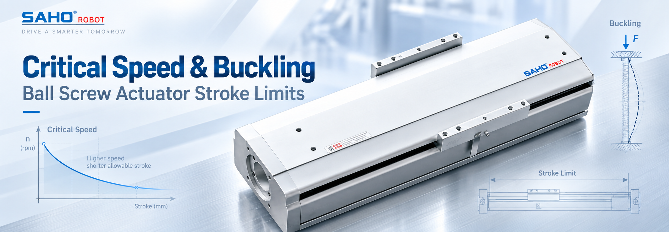
A long ball screw cannot be sized from stroke alone. Usable travel is constrained by two different stability boundaries: ball screw actuator critical speed, which limits rotational speed before shaft bending resonance becomes a concern, and ball screw buckling, which limits compressive axial load before a slender screw becomes unstable. Both become more restrictive as effective screw length increases, but they respond differently to shaft diameter, end support, rotational speed, and load direction. For a long-stroke actuator, define the real support and load conditions, check both boundaries independently, apply the required engineering margins, and use the more restrictive result.
Key engineering distinction: actuator stroke, unsupported rotating length, and compressed buckling length are related dimensions, but they are not automatically the same dimension. Using catalog stroke as the calculation length for both checks can produce the wrong conclusion.
What Inputs Define Ball Screw Actuator Critical Speed?
Ball screw critical speed is a structural-dynamic limit associated with the screw shaft's bending natural frequency. As a rotating shaft approaches a bending mode, small eccentricity, straightness error, alignment error, or imbalance can excite lateral vibration. The relevant boundary therefore comes from the screw as an elastic rotating shaft, not simply from the speed capability of the motor.
Simplified first-mode relationship
ncr = (60 / 2π) × (λ1² / Ln²) × √(EI / ρA)
In this simplified relationship, ncr is the ideal first critical speed, E is Young's modulus, I is the area moment of inertia, ρ is material density, A is shaft cross-sectional area, Ln is the effective unsupported rotating length, and λ1 represents the selected end-support boundary condition.
For a simplified solid circular shaft, critical speed scales approximately with shaft diameter / unsupported length². Length therefore has a strong influence: increasing the rotating span can reduce the speed boundary rapidly even when the required linear load has not changed.
A preliminary check should identify the applicable screw root or minimum shaft diameter, rotating unsupported length, actual screw shaft support condition, and highest screw rpm required by the motion profile. Required rpm may be derived from linear speed and screw lead, but the stability comparison itself is made against rotational speed.
Do not substitute motor maximum rpm for screw critical speed. A servo may be capable of a rotational speed that the selected screw should not use over its actual unsupported length. Final allowable speed requires the selected screw geometry, bearing arrangement, support condition, and engineering margin.
What Inputs Are Required for a Ball Screw Buckling Check?
Buckling addresses a different failure mechanism. When part of a long screw carries axial compression, the shaft can become laterally unstable before simple compressive stress appears excessive. A long-stroke screw that passes a rotational-speed check can therefore still be unsuitable for a heavily compressed layout.
Simplified Euler buckling relationship
Pcr = π²EI / (K × Lb)²
Here, Pcr is the ideal elastic buckling load, Lb is the length of the screw segment acting as a compression column, and K represents the effective-length factor created by its end restraints. For a circular shaft, theoretical buckling capacity scales approximately with diameter⁴ / effective length². Diameter therefore has a much stronger influence on buckling resistance than on critical speed.
A useful ball screw buckling calculation starts by identifying the maximum compression force at the screw, including relevant gravity, acceleration or deceleration, and process-force contributions. It must then identify which screw segment is actually in compression and how that segment is restrained.
The compressed length can vary with nut position. It may also be different from the unsupported rotating length used for critical speed. That distinction becomes especially important in long-stroke and vertical arrangements, where the force path changes as the nut travels.
Euler buckling is an idealized elastic-column model. Real ball screws also include thread geometry, bearing compliance, alignment tolerance, load eccentricity, and assembly effects. The applicable effective diameter, support factor, and safety factor should therefore follow the selected screw and actuator calculation method rather than a generic equation alone.
Which Limit Governs in Tension, Compression, and Vertical Layouts?
Critical speed and buckling are not competing versions of the same calculation. Critical speed asks whether the rotating shaft remains dynamically stable at the required rpm. Buckling asks whether a compressed shaft segment remains stable under axial load.
| Layout condition | Critical speed | Buckling | Main question |
|---|---|---|---|
| Tension-dominant segment | Check rpm against the effective unsupported rotating length. | Euler compression buckling is not the governing mode for a segment held in tension. | Is shaft speed safely below the permitted dynamic boundary? |
| Compression-dominant segment | Required. | Required using the worst relevant compression force and effective length. | Which stability boundary is reached first? |
| Vertical axis | Check according to rpm and unsupported rotating length. | Depends on the real force path; vertical orientation alone does not prove compression. | Which screw segment carries the load at each critical nut position? |
A vertical ball screw does not automatically work in compression
The locations of the fixed support, ball nut, and moving load determine whether gravity pulls the active screw segment into tension or pushes it into compression. Acceleration, deceleration, external thrust, and counterbalance forces can also change peak axial load. A vertical-axis review should therefore follow the physical force path rather than applying a blanket “vertical equals compression” assumption.
Practical decision sequence: identify the active screw segment at important nut positions, determine whether it is in tension or compression, calculate the compression case where applicable, check maximum rpm against critical speed, then apply the required engineering margins to each result separately. The more restrictive boundary governs.
Worked Comparison: How Length Can Shift the Governing Limit
The following calculation is illustrative only. It uses a simplified solid steel shaft and idealized pinned-pinned conditions to demonstrate the judgment process. These values are not SAHO product specifications, acceptance limits, or SDM Series ratings.
| Illustrative input | Assumption |
| Simplified shaft root-diameter approximation | 20 mm |
| Young's modulus / density | 210 GPa / 7,850 kg/m³ |
| Initial effective length | 1.20 m |
| Idealized end condition | Pinned-pinned |
| Required shaft speed | 1,200 rpm |
| Maximum compression load | 4.0 kN |
| Illustrative project speed margin | Operating speed ≤ 80% of calculated critical speed |
| Illustrative buckling safety factor | 2.0 |
At an effective length of 1.20 m, the simplified first critical speed is approximately 1,693 rpm. Applying the illustrative 80% speed margin gives a comparison boundary of about 1,354 rpm, so the required 1,200 rpm remains below it.
The corresponding ideal Euler buckling load is approximately 11.3 kN. Dividing by the illustrative safety factor of 2.0 gives approximately 5.65 kN, also above the 4.0 kN example compression load.
Now increase effective length to 1.40 m while keeping the simplified diameter and end conditions unchanged. Because both ideal critical speed and Euler buckling capacity scale with 1/L² in this example:
Critical speed: 1,693 × (1.20 / 1.40)² ≈ 1,244 rpm
Buckling load: 11.3 × (1.20 / 1.40)² ≈ 8.3 kN
The 80% example speed boundary is now about 995 rpm, so 1,200 rpm would no longer satisfy that assumed margin. The buckling comparison value after applying the example factor of 2.0 is approximately 4.15 kN, leaving the 4.0 kN compression case just below that boundary.
As the effective length increases: under these particular assumptions, critical speed becomes restrictive before buckling. A different diameter, compression load, support condition, or required rpm could reverse the result. The calculation demonstrates the judgment path only; it does not establish an SAHO product limit.
Common Mistakes When Defining a Long-Stroke Ball Screw Limit
One common mistake is treating a catalog rpm value as independent of screw length. Critical speed changes with unsupported rotating length and support condition. A speed that works for a shorter assembly may not remain acceptable after the bearing span becomes longer.
Another is using commanded travel as the calculation length without checking the real geometry. Stroke is not automatically unsupported length. Bearing locations, nut position, unused screw length, and support layout determine the span relevant to bending resonance.
The same issue appears in buckling calculations. The required length is the screw segment acting as a compression column in the load case being evaluated. Its worst value can occur near one end of travel, so the maximum buckling demand may occur at a different position from the maximum-speed case.
Support descriptions can also be oversimplified. Fixed-supported, fixed-fixed, or fixed-free are useful analytical models, but real assemblies include bearing stiffness, housing rigidity, mounting details, and tolerances. Final calculations should use the support factors and method applicable to the selected screw system.
For longer-stroke designs: if the requested axis becomes longer, determine which dimension actually increases—working stroke, bearing span, rotating unsupported length, compressed length, or several of them. Define these separately before deciding that the longer stroke is acceptable.
What to Define Before Selecting an SDM Configuration
Long-stroke actuator selection requires enough application information to evaluate both stability checks. A request containing only “stroke = 1,500 mm” does not establish whether rotational stability or compression stability will govern.
| Application data for a long-stroke ball screw | |
| Working stroke | Required usable travel and important operating positions. |
| Speed requirement | Maximum linear speed and, where known, maximum screw rpm. |
| Compression load | Moving load plus relevant gravity, acceleration/deceleration, and external axial process force. |
| Orientation | Horizontal, vertical, inclined, or another defined mounting direction. |
| Tension / compression direction | Identify how the active screw segment is loaded at important nut positions. |
| Support arrangement | Proposed motor-side and opposite-end support conditions. |
| Relevant screw lengths | Bearing span, unsupported rotating length, and maximum compressed length if known. |
| Axis drawing | Show motor end, support end, nut travel, load location, and gravity direction where applicable. |
If bearing spacing or compressed screw length has not yet been fixed, keep it as an open engineering variable rather than assuming that it equals the required stroke. Leave the final limit open until the actual screw and support arrangement are confirmed rather than assigning an unsupported value.
For the broader machine-level information that should accompany actuator selection, use the related guide to prepare a ball screw module selection checklist. That checklist complements the critical-speed and buckling review without replacing these two stability calculations.
When to Consider the SDM Series
Once stroke, rpm, compression load, orientation, and support arrangement have been defined, the SDM ball screw linear actuator series can be compared against the application requirements. The useful question at this stage is not simply whether a model has enough nominal travel. The selected screw and support arrangement must also satisfy the required rotational and compression boundaries.
If a candidate arrangement is already close to its critical-speed or buckling boundary, do not select a larger model only from frame size or catalog stroke. Submit the complete application condition so the screw size, support layout, and usable operating range can be reviewed together.
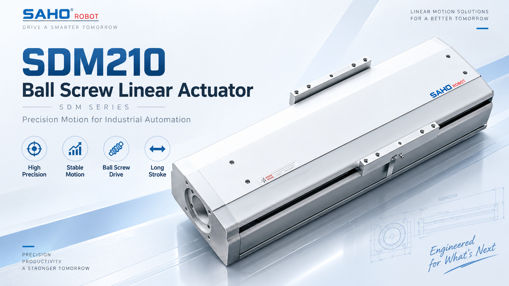
SDM210 Ball Screw Linear Actuator Shown as one product example within the SDM Series. The image does not imply that SDM210 is the correct model for a particular long-stroke application; final model selection depends on the actual stroke, speed, compression load, orientation, screw geometry, and support arrangement. View SDM210 Product DetailsCompare SDM Series |
When comparing actuator options: instead of asking only for “maximum stroke” or “maximum speed,” provide the required stroke and rpm together with the maximum compression case, orientation, and support layout. Ask for confirmation of the allowable combination for the selected screw arrangement. This prevents a catalog value from being interpreted outside the condition in which it applies.
Frequently Asked Questions
| Is critical speed the same as maximum motor speed? |
| No. Maximum motor speed describes drive capability. Ball screw critical speed is a shaft-dynamics boundary influenced by effective diameter, unsupported rotating length, and support condition. The screw can require a lower operating rpm than the motor is capable of producing. |
| When does buckling matter most? |
| Buckling matters most when a long, slender screw segment carries significant axial compression. Longer compressed length reduces theoretical buckling resistance, while shaft diameter and end restraint strongly influence the result. |
| Does a vertical ball screw always work in compression? |
| No. The force state depends on the positions of the fixed support, ball nut, and load, plus gravity, acceleration, and external forces. One vertical arrangement may place the relevant screw segment in tension while another places it in compression. |
| Why must the final limit come from the selected screw and support arrangement? |
| Because both critical speed and buckling depend on actual shaft geometry, effective length, end restraint, and required engineering margin. Generic calculations can screen a concept, but they cannot establish the final allowable stroke-speed-load combination for an unspecified assembly. |
Define the Stability Boundary Before Freezing the Stroke
For a long-stroke screw axis, the useful question is not simply “What stroke is available?” It is whether the required stroke can coexist with the required rpm and the worst compression case for the proposed support arrangement. The ball screw actuator critical speed check and the buckling check should therefore be completed before the machine layout turns bearing spacing and screw length into fixed constraints.
For an application review: provide the required stroke, maximum linear speed or screw rpm, complete moving load, maximum axial compression case, installation orientation, proposed end-support arrangement, relevant screw lengths, and an axis drawing. If any of these dimensions are still open, identify them so they can be considered as design variables rather than assumed limits.
Compare the SDM Series for Your Application Compare the SDM Series if the application requires a ball screw linear actuator, then provide the stroke, speed, load, orientation, support arrangement, and axis drawing so the final model and allowable operating boundary can be confirmed for the actual load case. Review SDM Series Ball Screw Linear ActuatorsContact SAHO for Engineering Review |





















