

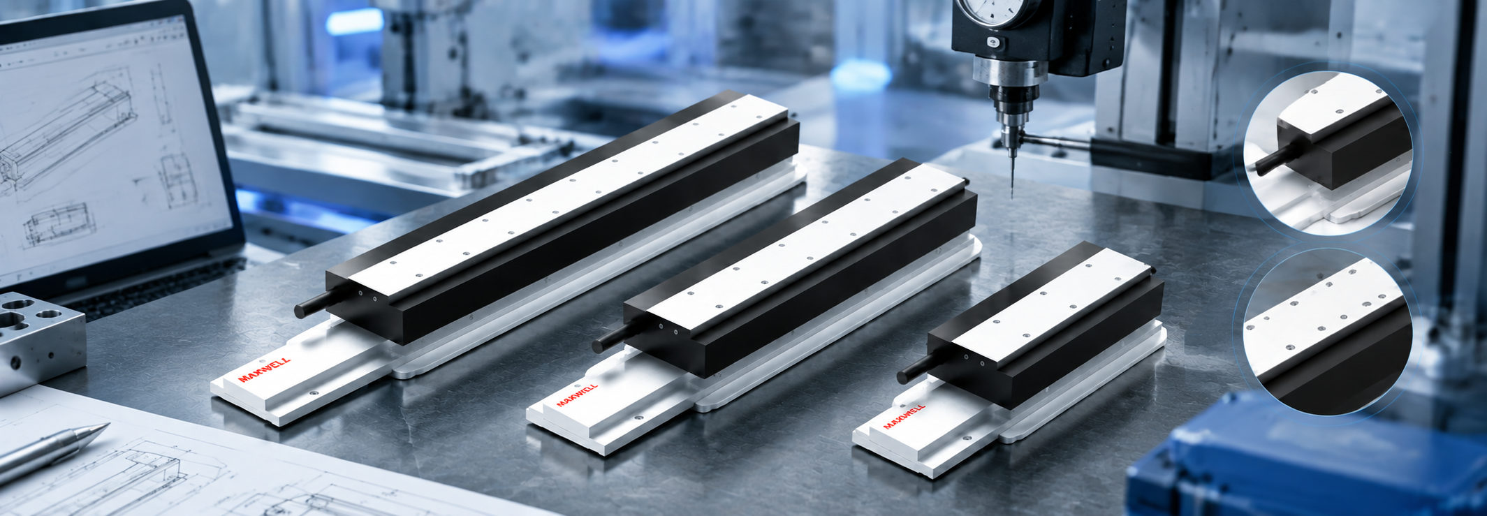
An MK linear motor can show an acceptable air gap at one point while the Mover-to-fixed-component alignment changes elsewhere along the stroke. Small differences in mounting-surface seating, guideway geometry, or fastening condition can affect clearance as the axis travels. That is why an MK linear motor air gap alignment inspection requires more than a single convenient reading. It must use the released drawing and controlling datums, measure at defined positions with an approved non-damaging method, and document the results against the project acceptance criteria. If the applicable air-gap limit, datum, or measurement method is unavailable, record engineering confirmation required rather than inventing a shop-floor limit.
Acceptance principle: treat air-gap validation as an evidence chain: correct drawing and revision → controlled datums → approved measurement method → readings at defined positions → recorded acceptance decision.
1. Define the Evidence Needed for an Air-Gap Acceptance
The inspection objective is not simply to produce an air-gap number. The record needs to show that the measured relationship between the Mover and the fixed motor-side component satisfies the requirement released for the actual machine assembly.
That distinction matters because the motor components are installed into a larger mechanical system. The guideway establishes the motion path, the machine structure establishes the mounting references, and the assembly fixture and fastening sequence can influence the final relationship. A gap that appears acceptable at one position does not automatically prove correct parallelism or alignment elsewhere.
| Acceptance evidence | What it must establish |
|---|---|
| Drawing control | The exact MK component identification, controlling drawing, revision, datum scheme, specified air gap, and permitted variation. |
| Measurement control | The approved measurement surfaces, tool or nonmagnetic spacer method, inspection positions, and assembly condition. |
| Stroke verification | The Mover-to-fixed-component relationship remains within the released requirement at all required inspection positions. |
| Acceptance record | Actual readings, instrument or spacer identification, setup condition, inspector, date, and the requirement used for the final decision. |
2. Confirm the Exact MK Drawing, Datum, and Assembly-Safe Condition
Before taking measurements, identify the exact MK component combination and the drawing revision released for the machine. MK and JKA are component families supplied as Mover & Stator / Magnetic Track components; they are not complete Linear Motor Stages or Linear Motor Modules. The Mover is the named motor component and should not be used as a synonym for the carriage, slider, or complete moving platform.
Do not automatically interchange stator and magnetic track. Use the terminology and interface definition shown on the product documentation or engineering drawing applicable to the exact assembly. The inspection sheet should then identify the mover-side datum, fixed-component datum, guideway reference, specified measurement locations, required fastening state, and acceptance criteria.
Engineers confirming the component direction can review the MK iron core linear motor range, but the product-family page does not replace the project drawing used for assembly acceptance.
Safety condition: magnetic attraction remains a mechanical hazard even when motor power is isolated. Use the project-approved fixture and restraint method, keep hands and loose ferromagnetic tools away from pinch areas, and do not rely on manual holding to control attracted components. If the safe assembly sequence or fixture requirement is unclear, engineering confirmation is required.
3. Establish Guideway and Magnetic-Track References Before Measuring
Air-gap measurement only becomes meaningful after the mechanical references are stable. The guideway controls the path followed by the OEM moving structure, while the motor components must be positioned relative to that path through the machine's defined mounting datums.
Start with clean, fully seated reference surfaces. Check for debris, burrs, uneven fixture contact, incomplete seating, or hardware that has not reached the specified inspection state. Any of these conditions can change the apparent gap without representing the final assembled geometry.
Next, confirm that the guideway and fixed motor-side component reference the intended machine datum. Do not shift a controlled datum merely to make one air-gap reading look better. Any correction should preserve the released datum hierarchy or be explicitly authorized by the responsible engineer.
Useful judgment: a gap that gradually opens or closes along travel is not just an isolated measurement problem. It can indicate a parallelism or reference-stack issue between the guideway motion and the fixed motor component. The inspection should capture that trend rather than averaging it away.
4. Measure the Air Gap at Defined Positions With an Approved Method
A reliable linear motor air gap measurement uses defined surfaces, defined positions, and a repeatable method that does not damage or significantly disturb the assembly. A feeler gauge may be appropriate for some mechanical inspections, but it should not be assumed suitable for every MK assembly. Material, access direction, insertion force, and possible magnetic interaction all need to be considered in the approved method.
| 1 | Restrain the assembly at the defined inspection position. Use the machine or fixture condition specified by the project before inserting or positioning the measurement tool. |
| 2 | Measure from the specified surfaces. Do not substitute a nearby cover, edge, coating, or convenient machined surface unless the drawing defines it as the inspection reference. |
| 3 | Use the approved non-damaging method. If a nonmagnetic spacer, gauge, or indirect dimensional method is specified, record exactly what was used. |
| 4 | Repeat at every required inspection point. Keep station identity and left/right or other lateral measurement locations separate if the drawing requires more than one reading per station. |
| 5 | Recheck in the final specified fastening condition. If loosening, shimming, repositioning, or retightening changes the geometry, repeat the affected measurements. |
Do not force the gauge. A measuring tool that deflects the Mover, guide structure, fixture, or fixed motor component can change the condition being measured. If the required contact force or allowable insertion method is not defined, engineering confirmation is required.
Illustrative measurement-spread calculation
Assume a project method produces five readings of 0.80, 0.82, 0.81, 0.83, and 0.81 mm. The observed spread is:
Maximum reading − minimum reading = 0.83 mm − 0.80 mm = 0.03 mm
This 0.03 mm result is illustrative only and is not an SAHO product limit. It describes the variation in the example data set. Acceptance still depends on whether the applicable project drawing permits each individual reading and the measured variation.
5. Check Mover-to-Track Alignment Through the Usable Stroke
Mover track alignment should be verified as a relationship through travel, not inferred from one static point. Move the OEM moving structure through the defined usable stroke or to the inspection stations specified by the project, using the approved safe handling condition.
At each position, record the air gap and observe whether the Mover-to-fixed-component relationship shows progressive opening, progressive closing, lateral drift, abnormal resistance, or any indication of contact. The pattern can help identify where the mechanical investigation should begin, but it does not create a new acceptance tolerance.
| Observed pattern | Inspection response |
|---|---|
| Similar readings at all required positions | Compare every reading with the project-approved requirement. Consistency alone does not prove acceptance if the absolute gap is outside the specified range. |
| Gap gradually opens or closes with travel | Review guideway-to-motor parallelism, datum relationships, mounting references, and any movement introduced during tightening. |
| Abrupt local change | Inspect the local mounting condition, seating surfaces, joints, contamination, fixture influence, or other project-specific causes. |
| Contact, interference, or unclear clearance | Stop the acceptance sequence and hold the assembly for engineering review. Do not continue travel simply to complete the inspection sheet. |
Do not use magnetic attraction as an alignment method. Attraction can pull the iron-core Mover toward the magnetic side, but it does not establish the required machine datum, guideway relationship, or parallelism. Geometry must come from controlled references, fixtures, and the approved fastening sequence.
Broader causes such as frame structure, feedback integration, cable routing, and other system-level issues are covered separately in common linear motor integration mistakes. The scope of this inspection remains narrower: verify and document the installed air gap and Mover-to-fixed-component alignment.
6. Record Readings, Setup, and the Project-Approved Acceptance Decision
A useful linear motor alignment inspection record should allow another engineer or technician to understand what was measured, how it was measured, and which requirement controlled the decision. A handwritten “gap OK” does not provide enough traceability for that purpose.
| Assembly identity | Machine or axis ID, MK component identification, controlling drawing, and drawing revision. |
| Reference setup | Datum references, guideway reference, fixture condition, restraint method, and fastener state. |
| Measurement method | Tool type, tool or spacer ID, calibration status where applicable, measurement surfaces, and approved method. |
| Position-by-position readings | Inspection station or coordinate, actual value, unit, and any required left/right or multi-point readings. |
| Alignment observation | Parallelism trend, local deviation, interference indication, visible shift, or “none observed.” |
| Traceability | Inspector, date, reviewer if required, and deviation or nonconformance reference where applicable. |
Use a controlled acceptance decision
The final status should connect directly to released criteria. A practical record can use three outcomes:
Accept: all required readings and alignment observations comply with the documented project criteria.
Hold for review: a reading, trend, interference indication, or assembly condition conflicts with the released requirement.
Engineering confirmation required: the necessary limit, datum, measurement method, drawing revision, or interpretation is missing or ambiguous.
After authorized adjustment: repeat every inspection point that could have been affected. A reading taken before loosening, shimming, repositioning, or retightening should not be carried forward as evidence of the final assembled condition.
7. Escalate Deviations Instead of Adjusting to Invented Limits
The location and timing of an unexpected reading can help narrow the investigation. If the gap gradually opens or closes along travel, review the guideway-to-motor relationship. If the reading changes after final tightening, examine surface seating and the approved fastening sequence. These patterns help identify possible causes, but they do not establish a new tolerance. Do not borrow acceptance limits from another MK size, motor family, or machine; the current assembly drawing and datum scheme still control the decision.
Escalation is appropriate when the specified gap is unavailable, the drawing revision is uncertain, the controlling datum cannot be identified, the measurement method is unclear, the gap changes unexpectedly through travel, or any contact or interference is observed.
Prepare this evidence before engineering review
| ✓ Exact MK component identification | ✓ Controlling drawing and revision |
| ✓ Datum and guideway reference scheme | ✓ Readings identified by inspection position |
| ✓ Tool or spacer identification | ✓ Measurement and restraint method |
| ✓ Final fastener and fixture condition | ✓ Photos or marked-up geometry where useful |
Do not close an inspection gap with an assumption. If the applicable limit, datum, or approved measurement method cannot be demonstrated from controlled project information, record engineering confirmation required and provide the measured evidence for review.
When to Continue From Inspection to MK Product Selection
Air-gap inspection confirms the assembled geometry; it does not determine which MK configuration a new machine should use. Product selection becomes the next step when the machine architecture has already been defined around iron-core Mover and fixed magnetic components and the engineering team needs to match the motor components to the machine's force, motion, packaging, guideway, feedback, and control requirements.
Do not select an MK model from air-gap considerations alone. Before comparing the MK family, prepare the required continuous and peak force, usable stroke, available installation envelope, duty cycle, guideway arrangement, feedback requirement, drive/control interface, and the mechanical drawing that defines the Mover and fixed-component mounting relationship.
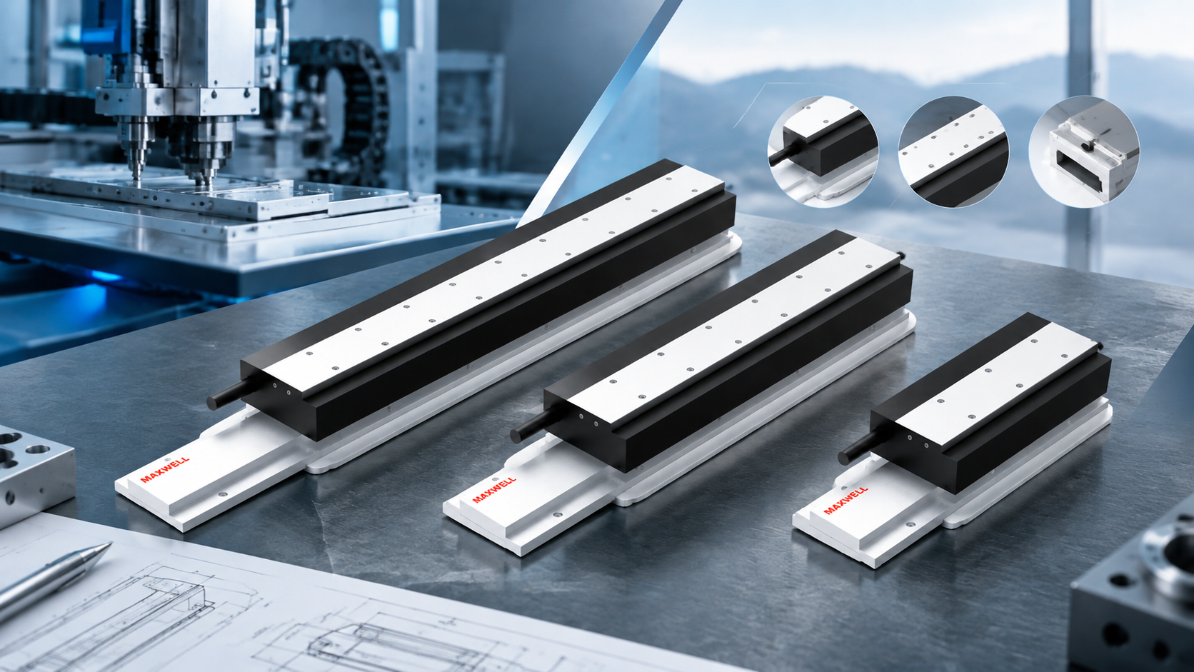 MK1 Iron Core Linear Motor Mover & StatorMK1 is shown here as a product example within the MK Series. Its appearance does not mean MK1 is automatically the correct choice for an assembly discussed in this guide. Confirm the required force, stroke, installation space, component dimensions, guideway arrangement, feedback, drive, controller, and project drawing before selecting a configuration. View MK1 Product Details View Full MK Series |
Information to prepare before requesting an MK recommendation
Required continuous and peak force based on the machine's actual motion and process load.
Usable stroke and the available space for the Mover and fixed motor-side components.
Guideway arrangement, machine mounting datums, and installation orientation.
Required motion profile, duty cycle, feedback arrangement, servo drive, and controller interface.
The assembly drawing showing the proposed Mover-to-fixed-component relationship and the intended air-gap inspection references.
Selection boundary: this article can help prepare the assembly evidence, but it should not be used to choose an MK model from an air-gap value alone. Where the required configuration, datum, or allowable assembly condition is not confirmed by the applicable documentation, request engineering confirmation before releasing the machine design.
Common Questions About MK Linear Motor Air Gap Inspection
| Can one air-gap reading represent the full stroke? |
| No. One reading describes only one position. Use the inspection positions defined by the project so parallelism errors or position-dependent variation through the usable stroke are not missed. |
| Which datum should control Mover and track alignment? |
| Use the datum scheme on the exact approved MK and machine assembly drawings. Do not replace it with a convenient guide edge, cover surface, or neighboring component. If the controlling datum is unclear, engineering confirmation is required. |
| Why must the measurement method be approved for the MK assembly? |
| The measurement tool and handling method can influence the result or damage the assembly. Near magnetic components, material choice, access direction, contact force, and restraint condition also matter. An approved method keeps the readings repeatable and comparable. |
| What belongs in an air-gap inspection record? |
| Record the assembly and MK identification, drawing revision, datum references, inspection positions, actual readings, approved method, instrument or spacer identification, fixture and fastener state, inspector and date, acceptance decision, and any deviation or engineering-review reference. |
Turn the Inspection Record Into a Clear Engineering Review
A complete MK linear motor air gap alignment inspection should leave no ambiguity about the drawing used, the datum relationship, the measurement method, the readings through the required stroke, or the basis for acceptance. That evidence is more useful than a single “good” measurement because it shows how the final assembly was validated.
If the machine is already being designed around iron-core Mover and magnetic-track components, review the MK Series against the actual machine requirements rather than choosing by a single dimension or inspection result. The final configuration still needs to be matched to the application's mechanical and motion data.
For a faster engineering review: send the exact MK identification or candidate configuration, controlling drawing and revision, datum scheme, air-gap readings by position, measurement method, tool or spacer information, final assembly condition, and any marked-up drawing or photos showing the deviation. For a new selection, also include the required force, usable stroke, motion requirement, duty cycle, installation space, guideway arrangement, feedback, drive, and controller information.
Ready to review the MK assembly or component direction? Review the MK Series if the machine is using iron-core linear-motor Mover and fixed motor components. If the air gap, datum, measurement method, or final configuration still needs confirmation, send the inspection record and application drawing to SAHO for engineering review before releasing the assembly. Review MK Series Iron Core Linear Motor Contact SAHO for Engineering Review |





















