

A belt actuator tooth jump becomes a credible explanation when a fast axis develops a sudden, persistent carriage-position offset during acceleration, deceleration, or reversal while the relevant motor-side position feedback remains repeatable. Belt tension alone does not explain that pattern. The more useful question is where the position relationship changed: in the feedback system, at the coupling or pulley, or between the timing belt and the carriage. A repeatable high-load trigger combined with a motor-to-carriage position mismatch and matching mechanical evidence is much stronger than any single symptom.
The key distinction: suspected tooth jump is a mechanical position-change event that should be supported by evidence. If the servo-side position repeats but an independent carriage reference changes, the transmission path becomes the stronger suspect. If position feedback itself becomes unstable, drops out, or reports a feedback-related fault, the feedback and servo system deserve attention before the belt does.
What True Belt Tooth Jump Usually Looks Like
Timing belt tooth skipping occurs when the belt temporarily loses correct engagement with the pulley and re-engages at a different tooth relationship. In a belt-driven servo axis, the practical result can be a carriage that no longer corresponds to the mechanical position expected from the motor-side reference.
The most useful symptom is not simply “the axis is inaccurate.” Look for a step change that appears immediately after a demanding part of the cycle. A typical investigation starts when the machine homes normally, runs several correct cycles, then loses process position after a rapid launch, hard deceleration, or direction reversal.
True belt tooth skipping becomes more plausible when several observations occur together:
The position loss appears during peak acceleration, deceleration, or reversal rather than during steady travel.
The physical carriage offset remains after the demanding motion segment has finished.
The fault becomes easier to reproduce with higher payload or more aggressive acceleration.
A brief mechanical sound or vibration occurs at the same motion point.
Inspection reveals tooth polishing, deformation, debris, tracking marks, pulley witness marks, or other localized evidence.
If the actual belt pitch is known from verified technical documentation, the measured carriage offset can be compared with the pitch and its multiples. A position change close to one or several tooth pitches can support the hypothesis, but it is not proof by itself. Coupling slip, pulley-to-shaft movement, or another mechanical interface can create the same kind of sudden position loss in a belt-driven axis.
Preserve the evidence: tightening the belt, changing servo gains, lowering acceleration, or cleaning the pulley may suppress the symptom while making the original cause harder to identify. The original event is most useful while its operating condition and mechanical evidence are still intact.
Tooth Jump vs. Encoder, Coupling and Servo-Following Faults
The fastest diagnostic question is: which relationship changed? Compare the commanded position, actual feedback position, physical carriage location, coupling relationship, and pulley relationship immediately before and after the event.
| Observation | What it suggests | Useful comparison |
|---|---|---|
| Motor-side position repeats, but the carriage has shifted. | Mechanical slip downstream of that feedback device becomes more likely. | Coupling, pulley-to-shaft connection, timing-belt engagement, belt attachment, and other transmission interfaces. |
| Encoder position becomes erratic, disappears, or triggers a feedback alarm. | An encoder, signal, connector, wiring, or feedback-system fault may be involved. | Feedback mounting, cable movement, connector integrity, signal quality, drive alarm history, and control settings. |
| Following error or torque demand rises sharply before position is lost. | The axis may be approaching a dynamic load or control limit before the mechanical event. | Acceleration demand, payload, binding, external resistance, available drive torque, tuning behavior, and the transmission. |
A slipping motor coupling or pulley-to-shaft connection can imitate a timing belt actuator fault very closely. Where the design permits safe access, place fine witness marks across accessible mating parts before reproducing the event. If the marks move relative to each other, the investigation should stay with that interface rather than moving directly to the belt teeth.
If the coupling and pulley witness marks remain aligned, the motor-side feedback returns to the expected value, but the carriage has physically shifted, the belt path deserves closer inspection.
Engineers already working with this product family can keep the JTG belt driven linear actuator page available as the product reference while the fault is being documented. The product page should support the investigation, not replace it.
Feedback location matters: a motor-mounted encoder reports motor position. A separate linear encoder attached to the moving carriage observes the output more directly. The meaning of “the encoder position is correct” therefore depends on where the feedback device is installed.
Why the Exact Motion Point Matters
Intermittent faults become much easier to understand when every event is tied to a precise operating condition. A record of the original motion, load, feedback and physical carriage position makes it possible to see what changed without relying on memory after the machine has already been adjusted.
| Motion point | Record the commanded start and end positions, approximate fault location, and whether the event occurs during launch, constant speed, deceleration, or reversal. |
| Direction | Note whether the event occurs in positive travel, negative travel, or both. Direction dependence can expose mechanical asymmetry. |
| Motion profile | Save velocity, acceleration, deceleration, and jerk where available. Preserve the original values before diagnostic reductions. |
| Moving load | Include payload, tooling, brackets, cables, hoses, and any recent production change that altered moving mass or resistance. |
| Servo evidence | Save commanded position, feedback position, following error, torque/current trend, and the exact servo alarm or warning if one occurs. |
| Physical reference | Measure the carriage against a repeatable machine reference before and after the event instead of relying only on the controller display. |
Why acceleration deserves special attention
The same axis can reach an identical top speed with very different peak transmission loads depending on how quickly it accelerates. Inertial force rises directly with moving mass and acceleration, which explains why a high acceleration belt actuator can appear normal during slow commissioning moves but lose position in production.
Illustrative calculation
F = m × a = 20 kg × 15 m/s² = 300 N
In this illustrative example, a 20 kg moving assembly accelerating at 15 m/s² creates 300 N of inertial force before friction, cable resistance, process forces, or other dynamic loads are added.
T = F × r = 300 N × 0.04 m = 12 N·m
If the effective pulley pitch radius were illustratively 40 mm, the corresponding inertial torque contribution would be 12 N·m. These values are examples only and are not SAHO product limits. Actual allowable torque, tooth loading, pulley geometry, belt condition, safety margin, and acceleration capability require engineering confirmation for the specific axis.
For broader machine-layout context—including moving mass, gantry architecture, acceleration, and integration conditions—review belt actuator applications and integration.
What Belt and Pulley Evidence Can Reveal
Once the fault data points toward a mechanical position change, the belt path often provides the most useful physical evidence. Tooth engagement, tracking, contamination and localized damage can help explain why the position shift appears at one part of the motion rather than throughout the entire cycle.
| 1 | Tooth engagement. Visible climbing, riding on tooth tips, or abnormal contact as the belt enters, wraps around, and leaves the pulley can point toward poor engagement. |
| 2 | Pulley alignment and tracking. Sideways belt movement, repeated flange contact, uneven edge polishing, or different tracking behavior after reversal can reveal an alignment problem. |
| 3 | Contamination pattern. Dust, chips, oily residue, or foreign material in the pulley grooves or tooth interface is more informative when its original location is documented before cleaning. |
| 4 | Localized belt and pulley damage. Tooth-face deformation, missing material, cracking near tooth roots, unusual polishing, frayed edges, groove damage, or fresh witness marks can narrow the likely failure mechanism. |
Pulley alignment is especially relevant when the fault is directional. Angular or lateral misalignment can change how load is distributed across the belt width, and a belt that looks centered while stationary may track differently under acceleration or reversal.
Contamination should also be treated as diagnostic evidence rather than simply a cleaning issue. If debris appears at one pulley or at a specific location associated with the fault, record that location. The distribution of contamination can help explain why belt tooth skipping occurs only at one part of the cycle.
Preserve what the machine is showing: belt condition, pulley grooves, tracking, contamination and witness marks are most useful before cleaning, retensioning, replacing parts, or disassembling the drive. Those observations may be the best evidence of the original fault.
Why Controlled Tests Matter More Than Guesswork
Controlled comparisons are useful because they show whether the fault follows a change in acceleration, direction, payload, or another stress factor. Changing one condition at a time keeps the evidence interpretable. Any reproduction testing still needs to follow the machine builder's normal safety procedures, with personnel clear of the moving axis and sufficient clearance for the commanded motion.
The original operating state. Initial motion parameters, servo settings, payload condition, and the physical carriage reference provide the baseline for every later comparison.
A reduced-acceleration comparison. If the same motion stops producing the fault when acceleration is reduced and other conditions stay similar, the mechanism is load-sensitive, but tooth jump is not yet proven.
Direction as a clue. A result that changes with travel direction can expose alignment, tracking, load-side, or coupling asymmetry.
Payload sensitivity. Where a safe comparison is possible, a profile that becomes more fault-prone with increased moving mass shows that dynamic load is part of the picture.
Command, feedback and mechanical position together. Commanded position, actual feedback, following error, torque/current trend, alarms, and final physical carriage location are most useful when they can be compared from the same event.
Witness marks after a reproduced event. Any relative movement across the coupling or pulley marks helps locate where the mechanical relationship changed.
Fresh belt-path evidence. New marks created during a controlled reproduction can be more informative than old general wear.
These comparisons are particularly useful when engineers need to distinguish belt tooth jump from a servo or feedback fault. When acceleration, payload, servo tuning, belt condition, and mechanical alignment all change at once, a disappearing fault becomes difficult to interpret. The machine may run again while the original cause remains unknown.
Reduced acceleration is a diagnostic tool, not automatically the final corrective action. A lower value may simply move the axis below the threshold at which poor engagement, contamination, tooth damage, pulley movement, or another mechanical weakness becomes visible.
This is different from routine maintenance: tension is part of the mechanical condition, but the question here is why position was lost. Product-specific adjustment or acceptance values should still come from the applicable technical documentation or engineering confirmation.
Reading the Symptoms Together
No single symptom proves tooth jump. The pattern becomes more useful when each observation is connected to the comparison that can strengthen or weaken a mechanical-slip explanation.
| Symptom | Most useful comparison | Interpretation |
|---|---|---|
| Carriage loses position only during hard acceleration. | Compare motor-side feedback endpoint with an independent carriage reference. | Repeatable motor position plus a shifted carriage strengthens the case for downstream mechanical slip. |
| Fault appears mainly after reversal. | Inspect belt tracking, pulley alignment, engagement, and coupling witness marks. | Direction-dependent mechanical evidence is more useful than the reversal symptom alone. |
| A sharp mechanical sound occurs with position loss. | Inspect tooth faces, pulley grooves, nearby interfaces, tooling, guides, and cable movement. | Sound supports the diagnosis only when it matches the mechanical evidence and fault timing. |
| Position loss becomes easier to reproduce with higher payload. | Compare the same motion profile at verified load conditions where safe. | The fault is load-sensitive, but the transmission, servo capacity, and other resistance still need to be separated. |
| Following error rises before the position shift. | Review torque/current, acceleration demand, friction, binding, and mechanical resistance. | The mechanical slip may be a consequence of a larger dynamic-load problem rather than the first event. |
| Homing restores the process position, but the error returns on the same move. | Measure the carriage immediately before homing and repeat the suspect motion segment. | A repeatable physical offset generated only after the high-load event supports a mechanical-change hypothesis. |
The strongest diagnosis usually combines several observations. For example, a reversal-related fault becomes much more persuasive when motor feedback remains repeatable, the carriage position changes, coupling witness marks stay aligned, and fresh belt or pulley evidence appears after the same motion.
When It Is a Local Fault—and When the Application Needs Review
Once the fault mechanism is understood, the next action depends on why the event occurred. If the investigation identifies contamination, damaged belt teeth, pulley movement, coupling slip, alignment evidence, or another localized mechanical defect, correct and verify that fault using the applicable service information.
The situation is different when no localized defect explains the event and the fault repeatedly returns at the payload and acceleration required by production. At that point, simply reducing acceleration may hide the symptom without answering whether the axis and application conditions are correctly matched.
| A local correction is more likely when | An application review is more useful when |
| A specific mechanical problem has been identified. The required production motion has not materially changed. Correcting the identified problem removes the position mismatch during controlled verification. | No clear local defect explains the repeated event. Payload, tooling, acceleration, cycle demand, or operating environment has changed. The required production point remains close to the condition that reproduces the fault. |
A different actuator is not the starting assumption. The important distinction is whether the existing axis has a correctable local fault or whether the required operating point needs a new application review. Product-specific load, acceleration, belt, pulley, environmental, and configuration limits require engineering confirmation.
Where the JTG Series Fits
Once the fault mechanism is clear, product selection becomes a separate engineering question. The JTG Series is relevant when the machine already uses a JTG axis or when a new belt-driven axis is being reviewed against a defined motion profile and operating environment. The fault evidence collected above provides useful context for that discussion without turning the diagnosis itself into a product recommendation.
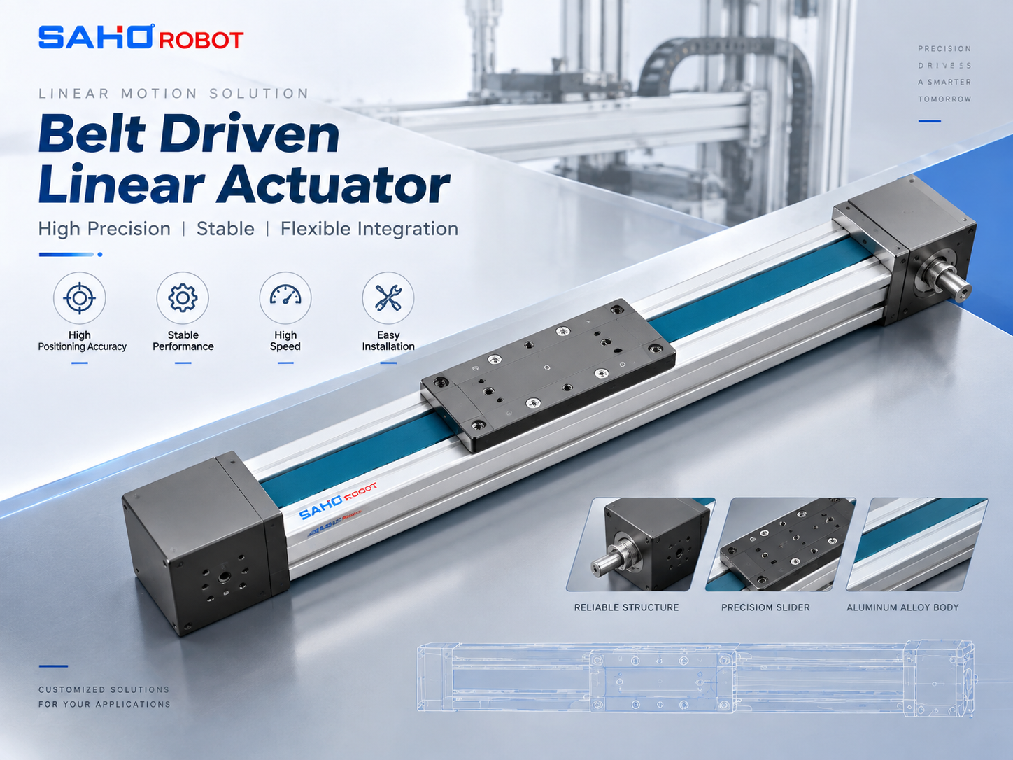 JTG Series Belt Driven Linear Actuator JTG100 is shown as a representative product image from the JTG family. Final model selection should be based on the required payload, stroke, speed, acceleration, installation condition, operating environment, motor arrangement, and the fault evidence collected above. View JTG Series |
What Matters When Discussing a JTG Configuration
The useful purchasing question is not “Which JTG model is bigger?” It is “What operating condition must the axis achieve after the fault mechanism has been removed?” That keeps procurement and engineering focused on the real machine requirement.
Required motion: stroke, travel distance, velocity, acceleration, deceleration, and cycle pattern.
Moving condition: payload, tooling, carriage-mounted equipment, cable or hose drag, and important changes between product variants.
Installation: axis orientation, motor arrangement, available machine space, and surrounding mechanical interfaces.
Environment: document dust, contamination, particles, splash, or other conditions that affect the axis selection.
Fault evidence: measured position loss, servo traces, alarms, pulley and belt photos, and witness-mark results.
When a model change does not solve the problem: if the position loss was caused by a loose coupling, damaged transmission component, feedback fault, or incorrect mechanical assembly, another JTG model does not address the original cause. Axis suitability can be reviewed against the production requirement after the identified fault is corrected.
What Makes an Engineering Review More Useful
The most useful engineering discussions start with enough context to reconstruct the event. “The belt slips during acceleration” says very little by itself; the operating condition, measured position change, servo evidence and visible mechanical evidence together make the problem much easier to understand.
| Information that helps with a JTG fault or application review | |
| ✓ JTG model or complete actuator identification | ✓ Motor and servo-drive identification |
| ✓ Required stroke and commanded move distance | ✓ Velocity, acceleration and deceleration |
| ✓ Moving payload and tooling condition | ✓ Fault direction and position in the stroke |
| ✓ Measured physical position offset | ✓ Commanded and feedback position traces |
| ✓ Following-error and torque/current data if available | ✓ Exact servo alarm text or code |
| ✓ Belt, pulley and tracking photos | ✓ Coupling and pulley witness-mark results |
| ✓ Notes on contamination or visible damage | ✓ Recent payload, tooling, process, or machine changes |
For gantry and Cartesian robot projects where the belt axis also carries another axis, cable chain, tooling, or cross beam, the related Belt Driven Linear Module for Gantry and Cartesian Robot Systems article adds application context.
For packaging and transfer-machine applications, the Belt Linear Actuator for Packaging and Transfer Systems article provides additional operating context.
Common Questions About Belt Actuator Tooth Jump
| What does belt tooth jump look like in position data? |
| It often appears as a sudden, persistent physical carriage offset after a demanding motion segment. If feedback is motor-side, the encoder may still report the expected motor endpoint because the position change occurred downstream in the mechanical transmission. |
| Can incorrect acceleration cause tooth skipping? |
| Excessive acceleration can increase inertial force and peak transmission demand enough to expose insufficient tooth engagement or another mechanical weakness. Acceleration should therefore be treated as a contributing operating condition, not automatic proof of the root cause. |
| How can tooth jump be separated from an encoder fault? |
| Compare the feedback signal with an independent physical carriage reference. Repeatable motor-side feedback with a shifted carriage points toward downstream mechanical slip. Unstable, implausible, interrupted, or alarm-producing feedback points toward the feedback path and should be investigated there first. |
| What information is most useful for a JTG fault review? |
| A useful review includes the JTG identification, motor and drive information, motion profile, payload, fault direction and stroke position, measured physical position loss, servo alarms, available feedback and torque/current traces, plus clear photos of the belt, pulley, coupling, tracking condition, and witness marks. |
From Diagnosis to the Right Engineering Next Step
A credible belt actuator tooth jump diagnosis connects three things: the operating condition that triggers the fault, a measurable change between feedback and physical carriage position, and mechanical evidence in the transmission. Once those relationships are clear, the next step is also clearer: correct a confirmed local fault, or review the complete axis application if the required production condition remains the limiting factor.
A faster engineering review usually starts with: the actuator model, stroke, payload, velocity, acceleration, installation condition, servo information, measured position loss, alarm record, feedback traces, witness-mark results, and belt/pulley photos. If the application requirement has changed, the new production cycle is useful context as well.
Ready to review the axis? Open the JTG Series page if this belt-driven product direction matches the machine, or send the diagnostic package to SAHO so the fault evidence and required production motion can be reviewed together. View JTG Series Contact SAHO for Engineering Review |





















