

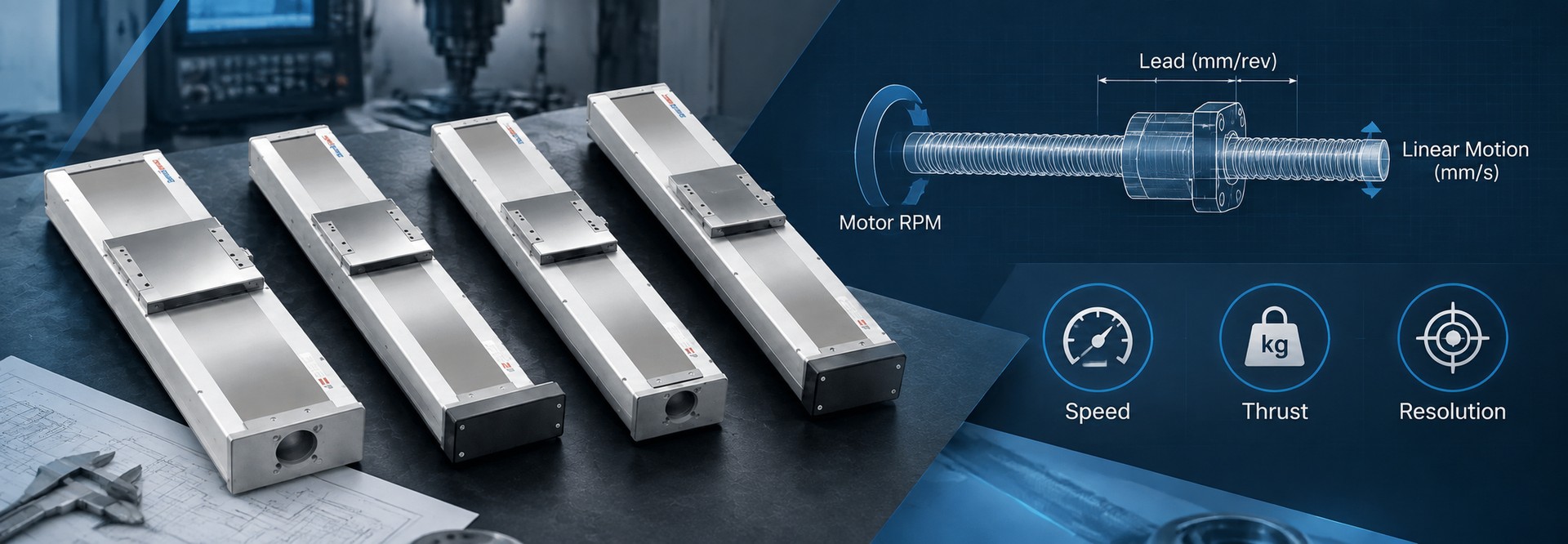
A ball screw lead calculation can work in either direction: calculate the required lead from target linear speed and screw rpm, or use a known lead to calculate the resulting linear speed. Once the lead is defined, engineers can also estimate theoretical axial force from torque and efficiency and translate encoder counts into nominal linear travel. A larger lead produces more travel per revolution and requires less screw rpm for the same linear velocity, but it also reduces theoretical thrust at the same screw torque and increases the travel represented by each encoder count. These relationships provide a practical first check before a screw-driven axis moves into actuator selection.
Core calculation path: use L = 60 × v / ns for required lead when target linear speed and screw rpm are known, v = L × ns / 60 for linear speed from a known lead, F = 2,000π × η × Ts / L for theoretical axial force when lead is in mm/rev, and Δx = L / (C × G) for nominal travel per encoder count. Keep lead units, gear ratio, torque location, and encoder-count definition consistent throughout the calculation.
1. Start the Ball Screw Lead Calculation With Lead, Not Pitch
Ball screw lead is the axial distance the nut travels during one complete screw revolution. A screw with a 10 mm lead therefore produces 10 mm of nominal linear movement for every full revolution of the screw.
| Lead | Linear travel per screw revolution. This is the value used in speed, thrust, and travel-per-count calculations. |
| Pitch | Axial spacing between adjacent thread forms. Pitch equals lead only for a single-start screw. |
| Gear ratio G | Motor revolutions per screw revolution in the equations used here. Direct coupling means G = 1. |
For a single-start ball screw, lead and pitch are numerically identical. For a multi-start screw:
Lead = Pitch × Number of Starts
A two-start screw with a 5 mm pitch therefore has a 10 mm lead. Entering 5 mm into the motion equations would produce incorrect speed, thrust, and travel-per-revolution results even though 5 mm correctly describes the thread pitch.
Unit check: use mm/rev consistently for the speed and encoder-scaling equations below. For torque-to-force calculation, either convert lead to meters or use the mm-specific force equation in Section 3. Accidentally mixing millimeters and meters changes the result by a factor of 1,000.
2. Calculate Linear Speed From Lead and Rotational Speed
The basic ball screw speed calculation connects screw lead with screw rotational speed:
v = L × ns / 60
where v is linear velocity in mm/s, L is ball screw lead in mm/rev, and ns is screw rotational speed in rpm.
When target linear speed and screw rpm are known first, rearrange the same relationship to calculate the required ball screw lead:
L = 60 × v / ns
For a target velocity of 300 mm/s and a screw speed of 1,800 rpm, the calculated lead is 10 mm/rev. A calculated value should then be compared with the lead options actually available for the selected ball screw or actuator.
With a 10 mm lead and a screw speed of 1,800 rpm:
v = 10 × 1,800 / 60 = 300 mm/s
In machine design, the target linear speed is often known first. Rearranging the relationship gives the required screw rpm:
ns = 60 × v / L
For a target velocity of 250 mm/s with a 10 mm lead, the required screw speed is 1,500 rpm. If lead is reduced to 5 mm while linear velocity stays unchanged, required screw speed becomes 3,000 rpm. If lead increases to 20 mm, required screw speed falls to 750 rpm.
This relationship is one of the quickest ways to reject an unsuitable preliminary lead. A smaller lead may look attractive from a theoretical thrust or resolution perspective, but it can require significantly higher rotational speed to achieve the same machine velocity. Treat the calculated screw rpm as a kinematic requirement only; before accepting the lead, verify the resulting rotational speed against the applicable ball screw operating limits for the actual screw diameter, unsupported length, and support arrangement.
Include the motor-to-screw ratio when motor rpm is not screw rpm
When the motor and screw rotate at different speeds:
ns = nm / G
v = L × nm / (60 × G)
This is the practical motor rpm to linear speed calculation. In this article, G means motor revolutions per screw revolution. A 2:1 reduction therefore means G = 2.
If this calculation is being used to pre-check an SDM project, the resulting lead, stroke, target velocity, and required screw rpm can later be carried into the SDM ball screw linear actuator review. At this stage, however, the calculation should still be treated as an engineering relationship rather than a final model recommendation.
3. Estimate Theoretical Axial Force From Torque, Lead and Efficiency
The ball screw lead and thrust relationship follows from rotational work converted into linear work. During one revolution, rotational input work is related to the linear work produced at the nut.
Rotational input work is 2πT, while linear output work is F × L. Including the assumed screw conversion efficiency gives:
F = 2π × η × Ts / L
In that form, L must be expressed in meters per revolution. For lead entered directly in mm/rev:
F = 2,000π × η × Ts / L
where F is theoretical axial force in newtons, Ts is torque available at the screw shaft in N·m, η is the assumed screw efficiency as a decimal, and L is lead in mm/rev.
Using illustrative values of 1.2 N·m screw torque, 10 mm lead, and an assumed efficiency of 0.90:
F = 2,000π × 0.90 × 1.2 / 10 ≈ 679 N
This is a theoretical ball screw thrust calculation, not a verified actuator load rating. The torque input should represent torque actually available at the screw under the operating condition being evaluated.
When a gearbox or other reduction sits between the motor and screw, a simplified screw-torque relationship is:
Ts = Tm × G × ηg
Here, Tm is motor torque and ηg is the assumed transmission efficiency. This step prevents a common error: entering motor torque as though it were screw-shaft torque while also applying the reduction ratio elsewhere.
What lead changes when screw torque stays constant
With screw torque and efficiency held constant, theoretical axial force is inversely proportional to lead. A 5 mm lead theoretically produces twice the axial force of a 10 mm lead at the same screw torque. A 20 mm lead produces half as much.
Do not turn calculated thrust into a product rating. The real axis requirement also depends on moving mass, acceleration, installation direction, external process force, the motor operating point, and an appropriate safety factor. If these inputs are not yet defined, use engineering confirmation required rather than hiding uncertainty inside an arbitrary margin.
4. Convert Encoder Counts Into Nominal Travel Increment
Ball screw lead also defines how rotational feedback maps into nominal linear movement. This relationship is useful for controller scaling and an initial ball screw resolution check.
If an encoder provides C effective counts per motor revolution and G is motor revolutions per screw revolution:
Δx = L / (C × G)
For direct drive, G = 1. With an illustrative 10 mm lead and 20,000 effective counts per motor revolution:
Δx = 10 / 20,000 = 0.0005 mm = 0.5 µm/count
That value describes the nominal linear travel represented by one effective feedback count. It does not mean the complete axis has ±0.5 µm positioning accuracy, 0.5 µm repeatability, or guaranteed mechanical movement at every individual count.
Resolution and positioning accuracy are different questions. The calculation describes electronic and kinematic scaling. Actual positioning performance depends on the complete mechanical, feedback, control, thermal, and measurement system.
Define what “encoder counts” means before calculating
Encoder documentation may refer to physical lines, pulses, quadrature counts, interpolated positions, or effective feedback counts inside the drive. A controller may then apply separate electronic gearing to command units. Before using the equation, document exactly what C represents.
If the feedback device measures screw rotation directly rather than motor rotation, it is often clearer to express C as effective counts per screw revolution. The important rule is that the feedback count basis and the lead value must ultimately refer to the same screw revolution.
Common controls mistake: do not mix encoder line count, drive feedback count, and command-pulse resolution in one formula. A very small calculated number is meaningless if the count definition does not match the actual scaling layer being evaluated.
5. Worked Example: One Lead Across Speed, Force and Resolution
The following calculation is illustrative only. These values are not SAHO product specifications, ratings, or acceptance limits. Their purpose is to show how one candidate lead affects several motion relationships at the same time.
| Illustrative input | Value |
| Ball screw lead | 10 mm/rev |
| Screw speed | 1,800 rpm |
| Torque at screw | 1.2 N·m |
| Assumed screw efficiency | 0.90 |
| Effective encoder counts | 20,000 counts/motor rev |
| Gear ratio | G = 1 |
Step 1 — Calculate linear speed
v = 10 × 1,800 / 60 = 300 mm/s
Step 2 — Estimate theoretical axial force
F = 2,000π × 0.90 × 1.2 / 10 ≈ 679 N
Step 3 — Calculate nominal travel per encoder count
Δx = 10 / 20,000 = 0.0005 mm = 0.5 µm/count
The same screw produces 10 mm of nominal travel for every screw revolution because its lead is 10 mm/rev.
What changes if the lead changes?
| Lead | Speed at 1,800 rpm | Theoretical force | Travel per count |
|---|---|---|---|
| 5 mm/rev | 150 mm/s | ≈ 1,357 N | 0.25 µm |
| 10 mm/rev | 300 mm/s | ≈ 679 N | 0.50 µm |
| 20 mm/rev | 600 mm/s | ≈ 339 N | 1.00 µm |
The comparison shows why lead should not be selected from one target alone. A designer focused only on linear speed at fixed rpm may prefer a larger lead. A designer looking only at theoretical thrust or nominal travel per count may prefer a smaller lead. The complete motion requirement has to satisfy all of these relationships together.
It is also useful to hold linear velocity constant instead of holding rpm constant. At a target of 300 mm/s, a 5 mm lead requires 3,600 rpm, a 10 mm lead requires 1,800 rpm, and a 20 mm lead requires 900 rpm. The machine speed is unchanged, but the screw-speed requirement changes substantially.
Comparison rule: identify what remains constant before comparing two lead values. Fixed screw rpm, fixed linear velocity, fixed screw torque, and fixed motor torque are different comparison conditions and can lead to different engineering conclusions.
6. Decide Whether a Larger or Smaller Lead Better Fits the Motion Requirement
There is no universally correct high-lead or low-lead choice. The useful question is whether the candidate lead keeps the required linear speed, screw rpm, theoretical force, and control scaling compatible with the same axis concept.
| A smaller lead tends to | A larger lead tends to |
| Reduce linear travel per revolution. Require higher screw rpm for the same linear speed. Increase theoretical axial force for the same screw torque. Reduce nominal travel per encoder count. | Increase linear travel per revolution. Require lower screw rpm for the same linear speed. Reduce theoretical axial force for the same screw torque. Increase nominal travel per encoder count. |
For an OEM engineer, this creates a straightforward judgment path: begin with the required machine motion, calculate what each candidate lead demands from the screw and motor, and only then move into product selection.
| 1 | Define the machine requirement. Record effective stroke, target velocity, move distance, and the motion condition that matters to the production cycle. |
| 2 | Calculate required screw rpm. Test whether the candidate lead produces a sensible rotational-speed requirement for the intended motor and transmission arrangement. |
| 3 | Estimate torque-to-force conversion. Use torque available at the screw, candidate lead, and the stated efficiency assumption. |
| 4 | Check feedback scaling. Calculate nominal travel per count while keeping that result separate from the actual positioning requirement. |
| 5 | Move into actuator review only after the relationships agree. A candidate lead should make sense for speed, rpm, force, and scaling before it becomes an actuator-selection input. |
7. Prepare Lead, Stroke, Speed and Load Data for Product Review
A useful ball screw lead calculation should end with a reviewable set of application data rather than a lead number by itself. “10 mm lead” or “300 mm/s” does not show the assumptions that produced the result or whether another requirement conflicts with it.
Before discussing an actuator configuration, prepare:
Effective stroke: actual working travel in millimeters.
Target linear speed: required velocity, preferably with move distance and target move time.
Candidate ball screw lead: lead in mm/rev and the calculation used to reach it.
Calculated screw rpm: required rotational speed at the target linear velocity.
Motor and transmission data: planned motor speed, applicable torque information, and gear ratio if used.
Moving load and installation direction: moving mass together with axis orientation.
External axial force: any process force acting along the motion direction.
Feedback definition: effective encoder counts, command units, or another clearly stated count basis.
Positioning requirement: the actual process requirement, kept separate from calculated travel per count.
Calculation assumptions: efficiency, gear ratio, safety factor, and other assumptions used in the preliminary calculation.
When is the calculation ready to move into product review?
| Ready for product review | Confirm more data first |
| Required stroke and linear speed are defined. A candidate lead has been checked against required screw rpm. Moving load and external axial force are known. Motor torque, speed, and any transmission ratio are identified. The positioning requirement is separated from encoder travel-per-count. | Lead was selected only because it gives a preferred resolution number. Motor rpm is being treated as screw rpm despite an undefined transmission ratio. Moving load or process force is still unknown. Available screw torque has not been established. Calculated travel increment is being treated as guaranteed positioning accuracy. |
This is the point where the calculation guide should hand off to product selection rather than expanding into a complete actuator-sizing article. For the wider application handoff, use the ball screw module selection checklist to organize the additional application information needed before final configuration review.
Practical handoff rule: submit the calculated lead together with stroke, target speed, screw rpm, moving load, external axial force, motor data, transmission ratio, feedback definition, and positioning requirement. A lead number without those conditions is not enough for a reliable engineering review.
Compare the Screw-Drive Product Direction After the Motion Relationships Are Defined
Once the calculation confirms that a ball-screw-driven linear axis is the intended direction, the next task is not to recalculate lead again. It is to compare the calculated motion requirement with an actuator structure that fits the machine layout.
The SDM Series remains the primary product direction for this guide because the application planning is centered on a general ball screw linear actuator. If the machine program also needs to compare a European-standard ball screw drive series, the MSDM Series provides a second screw-drive direction to review.
| Start with SDM when | Also compare MSDM when |
| The project is being developed around the SDM ball screw linear actuator product direction. Lead, stroke, speed, load, and installation data are ready for review. The engineering team wants to move from preliminary calculation into model and configuration checking. | The same motion requirement is being compared against a European-standard ball screw drive series. The machine builder wants another standardized screw-drive product family to evaluate. Final lead, stroke, motor, load, and installation matching will still be confirmed from the real application data. |
Do not choose between SDM and MSDM from the product image. Carry the same application record into both reviews: candidate lead, required stroke, linear speed, screw rpm, moving load, external axial force, motor information, installation direction, and positioning requirement.
MSDM Series Ball Screw Drive Module Compare the MSDM Series when the project needs to evaluate a European-standard ball screw drive product family after the lead, stroke, speed, load, and motor requirements have already been defined. 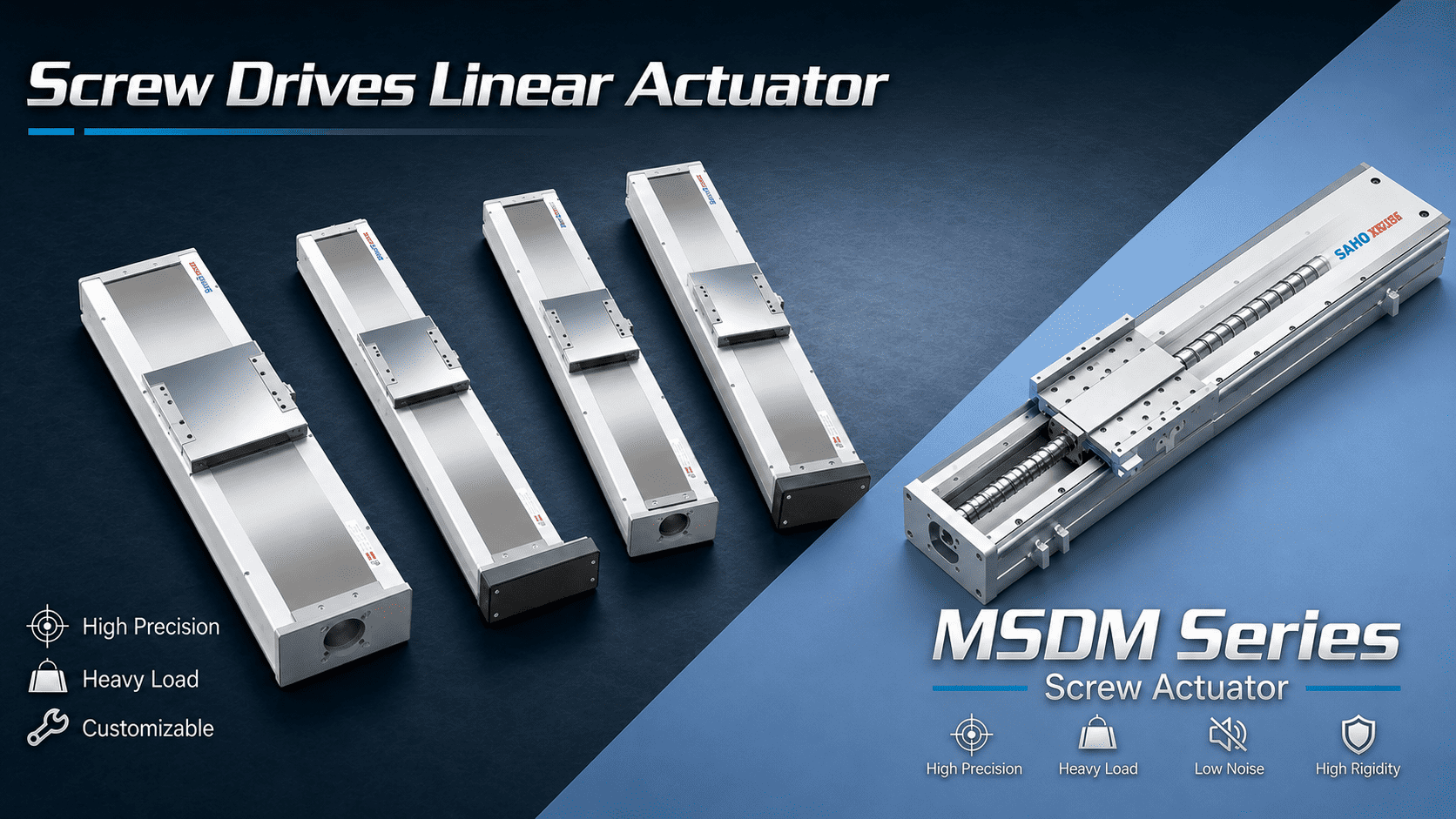 Use the calculated lead, required stroke, target speed, moving load, motor data, and positioning requirement as the comparison basis. Final configuration and application suitability require engineering confirmation. Compare MSDM Series Review SDM Series |
Ball Screw Lead Calculation FAQ
| Are ball screw lead and pitch the same? |
| Only for a single-start screw. Pitch is the axial spacing between adjacent thread forms, while lead is the axial travel produced by one complete screw revolution. For a multi-start screw, lead equals pitch multiplied by the number of starts. Motion calculations should use lead. |
| How does lead affect motor rpm? |
| For a fixed linear velocity, required screw rpm follows ns = 60v/L. A larger lead reduces the screw rpm required for the same linear speed, while a smaller lead increases it. Include the transmission ratio when motor rpm and screw rpm are different. |
| Does a smaller calculated increment guarantee better positioning accuracy? |
| No. A smaller value from Δx = L/(C × G) only represents a finer nominal electronic and kinematic travel increment. It does not establish complete system accuracy or repeatability. |
| What data should be checked before choosing an SDM lead? |
| Check required stroke, target linear speed, calculated screw rpm, moving load, external axial force, installation direction, available motor torque, transmission ratio if used, feedback scaling, and the actual positioning requirement. Then confirm whether the required lead and operating conditions correspond to an available SDM configuration. Engineering confirmation required. |
Take the Lead Calculation Into an Engineering Review
The useful output of a ball screw lead calculation is not simply “5 mm,” “10 mm,” or “20 mm.” It is a consistent set of relationships showing how the selected lead affects required rotational speed, theoretical axial force, travel per revolution, and nominal feedback scaling.
If those relationships now support a screw-driven axis concept, review SAHO’s ball screw actuator options for the primary SDM product direction. If a European-standard ball screw drive series is also relevant to the machine platform, compare the MSDM Series using the same application data rather than treating it as a separate calculation.
Before contacting SAHO for engineering review: prepare the effective stroke, target linear speed, candidate ball screw lead, calculated screw rpm, moving load, external axial force, motor torque and speed information, transmission ratio, installation direction, feedback-count definition, positioning requirement, and the assumptions used in the calculation. A preliminary axis drawing is also useful when available.
Have a Candidate Lead and Motion Requirement? Review the SDM product direction first, compare MSDM if the standardized product format is relevant, then send SAHO the calculated lead together with the stroke, speed, load, motor, transmission, feedback, installation, and positioning data for engineering confirmation. Review SDM Series Contact SAHO for Engineering ReviewProduct configuration, available lead, operating limits, and final application suitability require engineering confirmation. |





















