

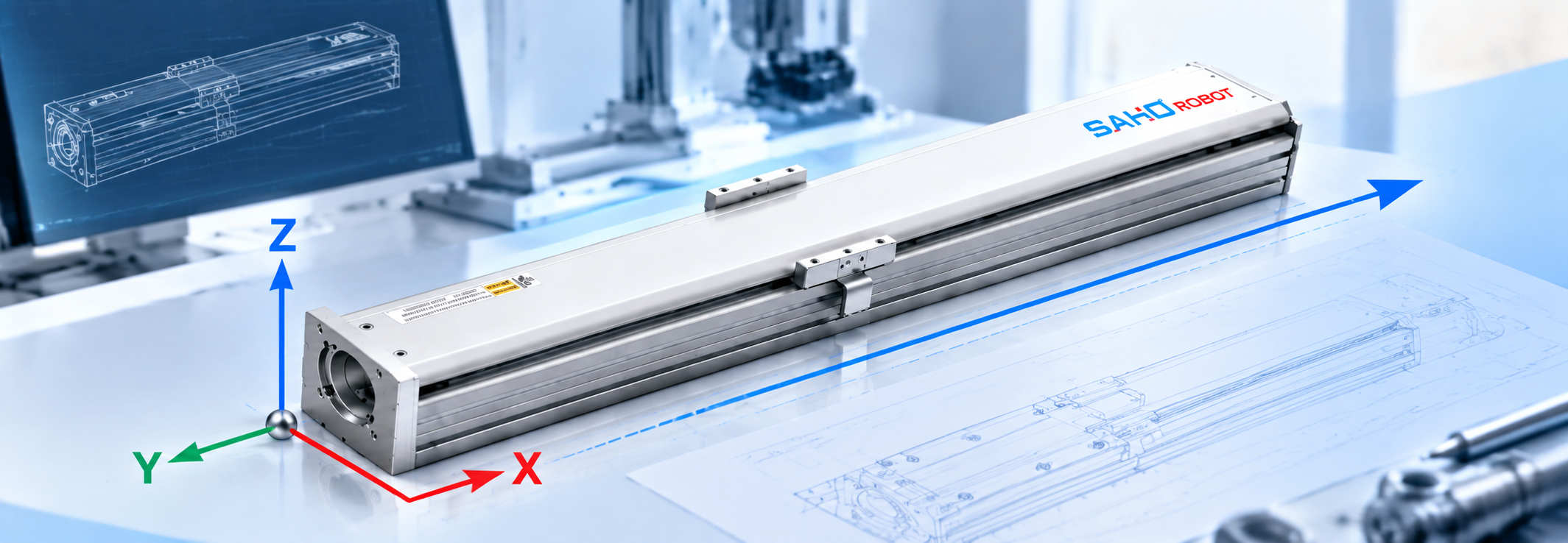
A reliable linear axis coordinate direction starts with one rule: define one machine coordinate convention before mechanical drawings, PLC logic, servo parameters, HMI labels, and commissioning procedures begin to use their own definitions. For every axis, document the axis name, observer viewpoint, positive and negative travel, machine origin, home reference, software limits, mechanical end positions, and expected feedback sign. Then use the same convention in CAD drawings, electrical documentation, PLC tags, motion programs, and commissioning records.
Practical rule: a positive command, positive physical travel, and increasing machine position should describe the same physical event. If mechanical, controls, and commissioning teams cannot all point to the same direction when they read “X+,” the coordinate interface is not yet complete.
Separate Machine, Work, and Axis Coordinates
The first integration decision is not where zero should be. It is which coordinate system a position belongs to. A value such as “+250 mm” is incomplete unless the drawing, PLC tag, motion program, or commissioning record also makes clear whether it refers to the machine frame, a work coordinate, or the local position reported by one axis.
| Machine coordinate | The stable reference frame for the complete machine or motion subsystem. Physical axis relationships, travel limits, diagnostics, and machine-level positions should remain understandable in this frame. |
| Work coordinate | A process, fixture, tooling, or product reference derived from the machine frame. It can change without redefining the physical direction of the machine axis. |
| Axis feedback position | The position reported by an individual axis. Its sign, zero, and scaling must map deliberately into the machine coordinate convention. |
Consider a transfer axis carrying a fixture between two stations. The machine may define a datum at machine X = 0, while the fixture center used by the process program is defined as work X = 0 when the carriage reaches machine X = +300 mm. Changing the fixture offset later should not redefine the physical machine direction.
Illustrative coordinate calculation
Xwork = Xmachine − 300 mm
At machine X = +425 mm, the work position is +125 mm. The offset changes the process reference, but it does not change the underlying machine axis direction.
Define Positive Travel from the Master Coordinate Frame and Document the Viewpoint
Positive travel is not automatically left-to-right. The master coordinate frame defines the positive axis direction; left and right are only observer-dependent descriptions. Document the selected positive travel direction with both a named viewpoint and a physical destination so drawings, controls, and commissioning records remain unambiguous.
| 1 | Choose the master coordinate frame. Use the machine, Cartesian, robot, CNC, or plant convention that the axis must integrate with. |
| 2 | Document the observer viewpoint. Use a defined reference such as operator side, machine front, or infeed side. |
| 3 | Describe a physical positive destination. For example, “toward Station B” or “away from datum plane A.” |
| 4 | Apply the definition to every interface. CAD arrows, jog commands, PLC values, HMI positions, software limits, and commissioning records should agree. |
A drawing note such as “X1+ moves the carriage toward Station B when viewed from the operator side” is stronger than an isolated X+ arrow. It remains understandable when somebody opens a mirrored subassembly drawing or approaches the equipment from the opposite side.
Motor rotation should not define machine direction
Motor rotation is an implementation relationship, not the machine coordinate definition. Two mechanically mirrored axes can require opposite motor directions while both still move in the same positive machine-space direction. The motor and encoder should therefore be mapped to the machine convention rather than used to create it.
| Use | Avoid |
| Machine X+ comes from the master frame. The observer viewpoint is named. The physical destination is stated. Motor and encoder signs are mapped afterward. | “Positive is toward the motor.” “Positive is to the right.” “Positive follows the encoder.” Different CAD and HMI direction definitions. |
Define vertical axes from the same master frame
Gravity does not determine the sign of a vertical axis. Follow the machine's governing coordinate convention first. Z+ upward is common in Cartesian machine coordinates, while some process coordinates use increasing depth downward. If the machine frame and process frame use different conventions, keep the machine definition stable and handle the difference with an explicit coordinate transformation.
Avoid one common mistake: do not change the machine axis sign simply because a motor is moved to the opposite end, a screw orientation changes, or a mirrored station is added. Those are hardware mapping changes, not automatically machine-coordinate changes.
Once the coordinate convention is stable, it can follow the machine regardless of the final actuator architecture. Engineers moving into hardware definition can review SAHO linear actuator solutions. If the drive principle has not yet been decided, use the separate guide to compare screw, belt and direct-drive axis designs rather than turning coordinate definition into a drive-selection decision.
Define Origin, Home, Software Limits, and Mechanical End Positions Separately
The words origin, home, and limit are often used as if they describe the same point. They may coincide on a particular machine, but the interface document should treat them as separate definitions.
| Axis origin | The zero point of the selected coordinate frame. |
| Home position | The reference established or reached by the homing procedure. It does not have to equal coordinate zero. |
| Software limit | A controller-defined normal motion boundary. |
| Mechanical end | A physical boundary of the mechanism. |
One axis can contain all of these reference points
| Mechanical End A | Negative Software Limit | Machine Origin | Positive Software Limit | Mechanical End B |
| − MACHINE TRAVEL + | ||||
The home reference can be located at machine zero, but it does not have to be. A controller may detect a sensor edge, move by an offset, and then establish the resulting machine coordinate. Documentation should therefore state both the physical homing reference and the coordinate expected after the sequence is complete.
Typical documentation conflict: a mechanical drawing labels the home switch “X = 0,” the PLC applies a home offset, and the HMI shows another zero after homing. Record the sensor location, homing direction, final home coordinate, and machine origin separately so each team is referring to the same thing.
Software limits should also remain distinct from mechanical ends. Required spacing between the normal working range, limit sensors, software boundaries, and physical end positions depends on machine speed, stopping behavior, control architecture, and mechanical design. If those values have not been established, leave them open for engineering confirmation rather than assuming a fixed margin.
Verify Motor, Encoder, and Commanded-Direction Signs at Low Speed
A coordinate convention is not complete until the real machine follows it. Commissioning should verify three separate relationships: the sign of the motion command, the physical direction of movement, and the sign of position feedback.
Start from a location with adequate clearance from tooling and travel ends. Use controlled low-speed motion and a small displacement appropriate to the machine. Confirm positive motion first, then repeat the observation in the negative direction. Safe speed, displacement, machine state, and stopping provisions should be set for the actual equipment.
| Test | Expected result | What to investigate if it disagrees |
|---|---|---|
| Positive jog | The carriage moves in the documented positive direction. | Review the intentional command-to-drive direction mapping. |
| Actual position | Reported machine position increases during positive travel. | Feedback polarity, scaling, or a coordinate transform may be inverted. |
| Negative jog | The carriage reverses and machine position decreases. | Check whether a sign correction has been applied at only one part of the control chain. |
| PLC and HMI | Both represent the same machine-coordinate sign. | Look for duplicate sign inversions, different source variables, or separate scaling logic. |
Fix one mapping layer deliberately
One of the easiest ways to create a difficult maintenance problem is to add negative signs wherever a value looks wrong. A drive parameter may invert one signal, PLC code may invert another, and an HMI expression may invert it again. The machine eventually appears to work, but recipes, software limits, diagnostics, alarms, or service screens can still use different coordinate meanings.
Commissioning check: correct the inversion at one intentional layer, document where that mapping occurs, and then repeat the positive and negative tests from the physical axis through to the value displayed on the HMI.
Create One Drawing, PLC, and Commissioning Handoff
A useful machine integration coordinate convention should be a shared engineering interface rather than a sentence buried inside one controls document. Mechanical, electrical, software, and commissioning teams should all be able to identify the same axis direction from the same controlled information.
| Axis identity | Use one stable axis name and function across CAD, electrical drawings, PLC logic, motion control, and HMI. |
| Viewpoint | State where the observer is located. Avoid unqualified left/right descriptions. |
| Positive travel | Add the positive arrow plus a physical destination such as “toward Station B.” |
| Origin / datum | Identify the physical reference and its relationship to machine zero. |
| Home definition | Record the homing reference, approach direction, offset logic, and resulting coordinate. |
| Travel boundaries | Distinguish working range, software limits, sensor limits where applicable, and mechanical ends. |
| Feedback sign | Confirm that machine position increases during documented positive travel. |
| PLC / HMI interface | Identify commanded position, actual position, home state, and limit-state tags using the project naming standard. |
| Revision | Record the controlling drawing number and revision. |
| Commissioning result | Record the positive/negative direction test and the accepted final mapping. |
The drawing should make sense without opening the PLC project
The general-arrangement or axis-interface drawing should show enough information for a mechanical engineer to identify the coordinate convention independently of the controls software. At minimum, show the axis ID, positive arrow, origin or datum, and named travel ends. Multi-axis equipment should also include a machine-level coordinate triad.
PLC tags should reinforce the drawing rather than create a separate meaning. A project may use tags such as AX_X1_CMD_POS and AX_X1_ACT_POS, but exact naming is a project standard rather than a product requirement. The important point is that every value has a known coordinate frame and sign.
Keep Mirrored and Multi-Axis Machines in One Coordinate Convention
Direction errors become more likely when several mechanically similar axes are installed in different orientations. A left-hand and right-hand station can have motors facing opposite directions while both axes still need the same machine-space positive direction.
Gantries create a similar situation. A master and slave axis may be mechanically mirrored, and their motor rotation or encoder polarity may differ. Those implementation differences should be resolved below the machine-coordinate layer so one positive gantry command still represents one coherent Cartesian movement.
| Keep common at machine level | Hardware mapping may differ |
| Axis letters and coordinate frame Positive Cartesian direction Machine origin definition Work-coordinate transformation Operator-facing position meaning | Motor rotation direction Drive direction parameter Encoder polarity Sensor mounting side Physical motor location |
Useful review question: if this axis were physically mirrored tomorrow, would X+, Y+, or Z+ still mean the same motion in machine space? If not, the coordinate definition may be tied too closely to hardware orientation.
Fixtures, cameras, nests, and tooling may still need their own local zeros. Use work-coordinate offsets for those process references rather than reversing the underlying machine axis simply to make one station easier to program.
Apply the Convention to a SAHO Linear-Axis Inquiry
Once the coordinate convention is stable, include it with the mechanical and controls information supplied for a linear-axis inquiry. This does not replace actuator sizing or drive-technology selection. It helps make clear how the axis must fit and behave inside the complete machine.
| Coordinate information to include with the application drawing | |
| ✓ Axis ID and machine function | ✓ Installation orientation |
| ✓ Defined observer viewpoint | ✓ Positive travel arrow |
| ✓ Machine zero / datum | ✓ Home or reference point |
| ✓ Required working positions | ✓ Negative and positive travel ends |
| ✓ Relevant sensor/reference locations | ✓ PLC or controller conventions |
If motor-side orientation, cable exit, sensor position, or another packaging constraint affects the machine layout, identify it on the same drawing. Any point that is still undecided should remain clearly marked for engineering confirmation instead of being treated as a fixed requirement.
When a product page becomes useful
Once the machine architecture has established that a screw-driven actuator is the right fit, the next step is to compare the required stroke, load, installation layout, positioning behavior, motor arrangement, and sensor requirements with an actual actuator series. The SAHO SDM Series is one relevant option for applications that already point toward a ball screw linear actuator.

SDM Series Ball Screw Linear Actuator A practical product option when the machine already requires a screw-driven automation axis. Compare the required stroke, moving load, installation orientation, positioning needs, motor layout, and sensor arrangement while keeping the machine coordinate convention independent from the final hardware orientation. |
If the project has not yet decided between screw, belt, or direct drive, compare the drive technologies first. The linear axis drive-technology comparison explains where each approach fits before you move into a specific actuator family.
What to prepare before asking for a quotation or engineering review
A coordinate drawing is valuable, but it cannot select an actuator by itself. Procurement and engineering teams should send two types of information together: the interface definition from this article and the basic application data required to review the physical axis.
| Coordinate and interface data | Application data for engineering review |
|---|---|
| Axis name and function Machine coordinate direction Observer viewpoint Origin and datum Home/reference definition Working positions Software and physical travel ends Motor/cable orientation constraints PLC or controller convention | Moving load and tooling Required usable stroke Target motion and cycle information Installation direction Required positioning behavior Working environment Motor/controller preferences where already fixed Machine envelope and mounting constraints |
Procurement check: do not approve a model only because its nominal stroke appears to cover the process distance. Confirm how the required working positions, home approach, datum relationship, software limits, mechanical ends, tooling clearance, and machine envelope appear together on the axis drawing. Final model and configuration selection should use the complete application data.
Before releasing the interface: ask a mechanical designer, controls engineer, and commissioning engineer to identify the same physical movement from the notation “X+.” If the drawing alone does not allow them to reach the same answer, the coordinate definition still needs work.
Common Questions About Linear Axis Coordinate Direction
| Is positive travel always left to right? |
| No. Positive direction follows the master coordinate frame. Left and right depend on the observer's position, so document the viewpoint and add an arrow plus a physical reference such as “toward Station B” to remove ambiguity. |
| What is the difference between axis origin and home position? |
| The axis origin is zero in a coordinate frame. Home is the reference established by the homing procedure. The home sensor can be physically offset from machine zero, and the final home coordinate may include a programmed offset. |
| How should vertical-axis positive direction be defined? |
| Follow the machine's master coordinate convention rather than motor orientation or gravity. If a process needs a different downward-positive coordinate, represent that as a separate work or process coordinate. |
| What should be recorded in a machine coordinate handoff? |
| Record the axis ID, observer viewpoint, positive and negative travel, machine origin or datum, home reference and final home coordinate, software limits, mechanical ends, feedback sign, PLC/HMI interface, controlling drawing revision, and commissioning direction-test result. |
Define the Interface Before the Machine Reaches Commissioning
Coordinate problems are easiest to solve while the machine still exists as drawings and interface documents. Once mechanical assemblies, PLC logic, HMI screens, recipes, and acceptance procedures depend on different definitions, changing direction or zero becomes much more expensive.
A documented linear axis coordinate direction gives the machine designer and actuator supplier the same reference for installation orientation, datum location, home strategy, usable positions, sensor planning, and controls handoff. It also makes later model review more productive because unresolved coordinate questions are no longer mixed with product sizing questions.
For a faster engineering review: send the preliminary machine or axis drawing together with the coordinate handoff. Include the axis ID, positive direction, origin, home reference, required positions, travel endpoints, installation orientation, moving load, required stroke, motion requirements, and any motor, sensor, cable, or controller constraints already fixed by the machine design.
Ready to move from coordinate definition to axis review? Review SAHO linear motion products to narrow the suitable product direction. If the drive family or model still needs confirmation, send the coordinate drawing together with the application data so the mechanical and controls requirements can be reviewed as one machine requirement. |





















