

A reliable linear motor commissioning checklist starts with mechanical geometry and feedback, not servo gains. The safest sequence is mechanical inspection, encoder verification, low-current motion, controlled tuning, and full-cycle validation. This order separates installation faults from control problems before higher speed or acceleration makes diagnosis harder. More importantly, it creates a repeatable path from an assembled axis to stable production motion.
For direct-drive systems, small installation problems can appear immediately in motor current, following error, vibration, or settling. A tight guide can look like a tuning problem, while a noisy encoder can resemble mechanical instability. In practice, each commissioning stage should answer one specific question before the next stage begins. The axis should only progress when the previous condition is understood and repeatable.
Recommended sequence: confirm mechanics and feedback first; perform restricted low-speed motion second; tune dynamic response third; then validate temperature, cables, sensors, repeatability, and the complete production cycle.
5-Step Commissioning Checklist
Inspect mechanics: confirm mounting, guides, air gap, payload, cables, sensors, and clear travel before drive motion.
Verify feedback: confirm encoder direction, scaling, reference behavior, signal quality, and commutation setup before closing the loop for normal motion.
Begin restricted motion: use conservative current, speed, and acceleration for short low-speed moves in a clear section of travel.
Tune dynamic response: increase performance only after mechanics and feedback remain stable and repeatable.
Validate the full cycle: confirm settling, temperature, cables, sensors, repeatability, and process quality under representative production conditions.
Pre-Power Mechanical Inspection
Before the servo drive is enabled, the axis should already behave like a mechanically sound assembly. No servo parameter can correct loose hardware, distorted guides, a moving encoder bracket, restricted travel, or cable forces that change through the stroke.
Compare the installed axis with the machine drawing, including carriage orientation, payload position, motor and encoder location, sensor clearance, cable entry, and usable stroke. Where safe manual inspection is permitted, compare resistance at several positions and in both directions. Investigate any local tight point or cable pull before current is used to move through it.
For an integrated sealed linear motor module, the inspection focus shifts from building the motor-guide relationship to checking installation quality around the complete axis. Base flatness, mounting stress, payload position, external cables, sensors, and machine stiffness still matter. A complete module simplifies integration, but it does not remove the effect of an unsuitable machine base or poorly routed moving cables.
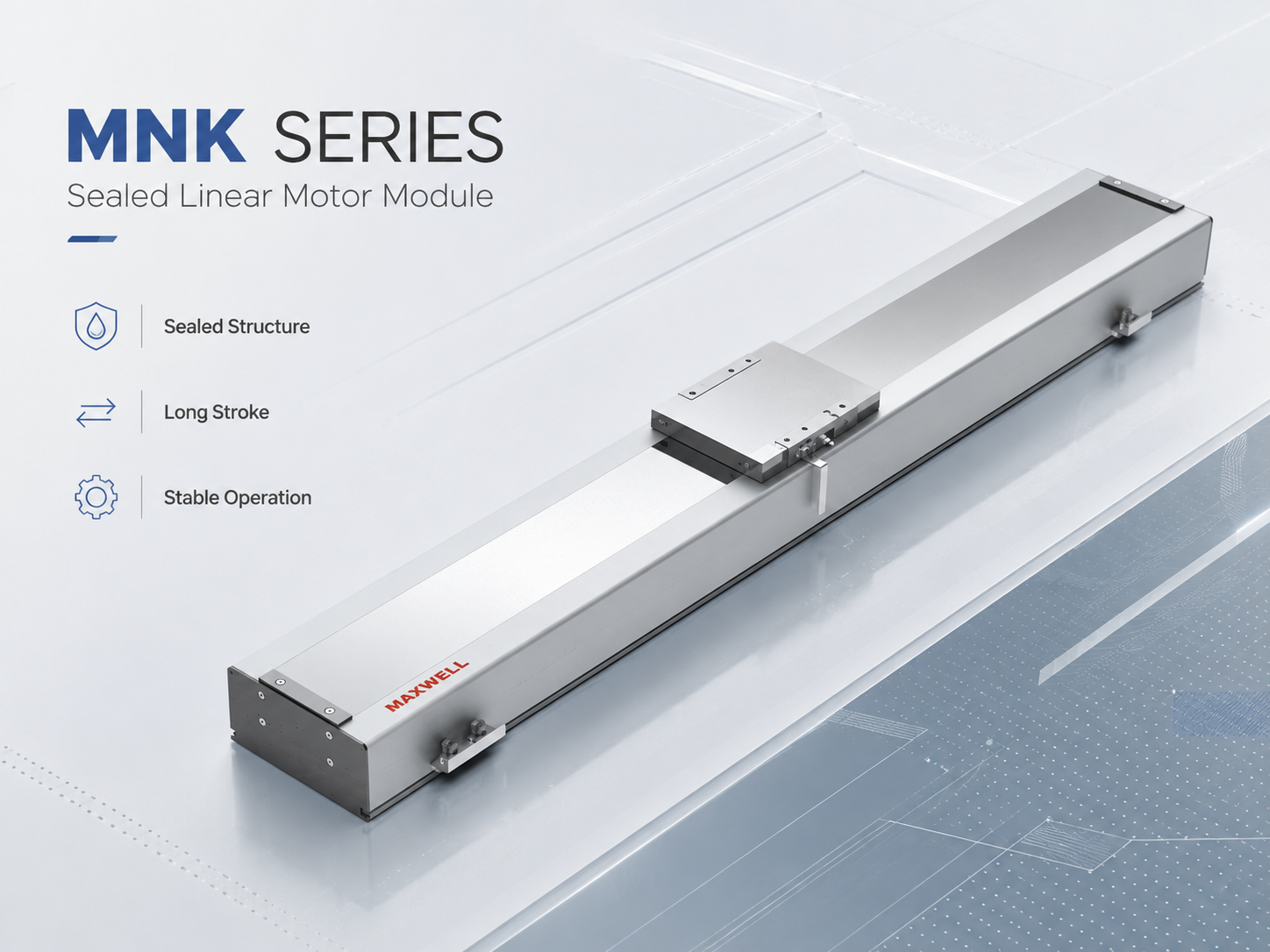 MNK module inspection should include mounting condition, payload installation, end clearance, sensors, and moving-cable behavior.
Keep restricted motion well inside the physical stops until direction is confirmed, and treat software limits as the normal operating envelope rather than the only protection. Whenever practical, inspect and later test the axis with the representative payload, fixture, cable package, and installation direction because off-center load, structural flex, gravity, and cable routing can change the result.
Vertical-axis safety: before enabling a vertical or inclined axis, verify the machine’s approved holding, counterbalance, braking, guarding, and safe-stop provisions. Do not rely on servo holding force alone to prevent uncontrolled movement after power loss or a drive fault. Emergency stops, travel limits, and drive safety functions should be validated according to the machine risk assessment and the installed drive documentation.
Before applying drive power, confirm these mechanical items:
Motor, guide, carriage, base, and payload fasteners are secure.
The usable stroke is free from mechanical contact or unexpected resistance.
Encoder scale and readhead brackets are firmly mounted.
Limit, home, and process sensors have adequate physical clearance.
Power, feedback, sensor, and cooling lines move without pulling the carriage.
Cable carriers remain free at both ends of the intended travel.
Payload position and installation direction match the planned machine configuration.
Protective earth, shielding, connectors, and strain relief are complete.
Record anything that differs from the released drawing. A thicker fixture plate, relocated sensor, changed cable entry, or off-center payload may look minor but can reduce usable stroke, change guide loading, or introduce a force that appears later in the current trace. If the axis will operate with several approved fixtures, identify which configuration is being commissioned rather than treating an empty carriage as representative.
Proceed when: the installed axis matches the released mechanical intent, the payload and cables are secure, travel is clear, and the safety provisions are ready for restricted motion. The next question is whether the motor, guides, encoder, and moving structure remain geometrically consistent throughout travel.
Alignment, Air Gap and Guide Resistance
Linear motor alignment involves more than making two visible edges parallel. Guide straightness, carriage attitude, motor mounting, stator position, encoder alignment, and machine-base geometry all affect the final force path. Because the motor drives the load directly, changes in that geometry can appear quickly in current demand or position response. The commissioning process should separate those effects before dynamic tuning begins.
Air gap should always follow the approved drawing or technical documentation for the selected motor. There is no useful universal air-gap value across different motor constructions. Instead, the important commissioning question is whether the required relationship stays consistent through the working stroke. Local contact, skew, or changing clearance should be corrected mechanically.
Guide resistance needs a similar position-by-position check. For example, a guide may move freely near the center but tighten near one end because of mounting distortion. Once the servo is enabled, that location may show increased current or following error. Increasing gain might reduce the visible position deviation, yet the underlying mechanical load remains.
Commissioning order: complete mechanical alignment, air-gap, guide-resistance, cable, and clearance checks before enabling servo motion. Verify encoder direction, scaling, reference behavior, signal quality, and the approved commutation setup before normal closed-loop travel. Only after these checks are confirmed should the axis perform short, low-current, low-speed moves for current-demand and position-response evaluation; higher speed, acceleration, and tuning come later.
A useful diagnostic method compares physical position with several controller signals. During a slow test later in the process, log carriage position, actual velocity, following error, and motor current. If an abnormal condition repeats at the same machine coordinate, inspect geometry before changing global tuning parameters. This simple comparison often shortens troubleshooting time.
Direction can provide another clue. Similar resistance in both directions often points toward a local mechanical condition. Different behavior during forward and reverse travel can indicate cable force, guide preload, gravity influence, or directional structural loading. The pattern matters more than a single current value.
For low-vibration positioning, a low-vibration ironless linear motor places greater emphasis on preserving the smooth force characteristic through the complete machine structure. Guide quality, encoder mounting, payload rigidity, and settling behavior remain central commissioning variables. A smooth motor cannot compensate for a flexible fixture or misaligned guide.
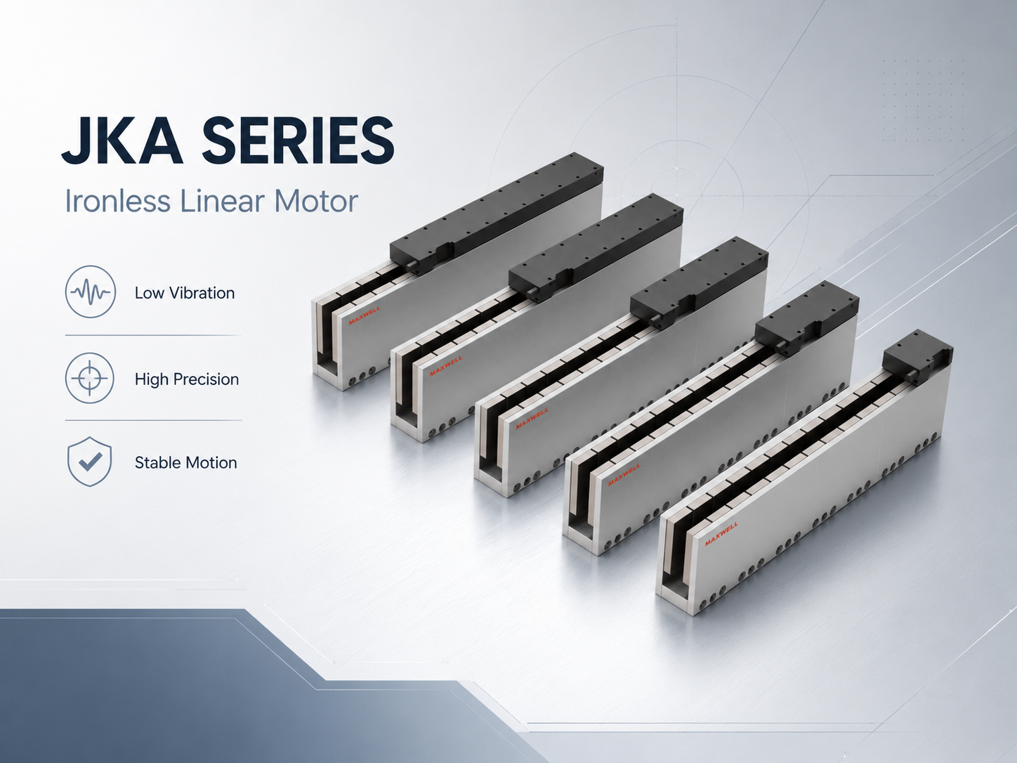 JKA applications require particular attention to guide quality, encoder stability, structural stiffness, and settling behavior.
Motor architecture changes the inspection emphasis. JKA and JKB use ironless motor designs, while WJM and WKM use iron-core designs; MNK is an integrated stage. The installed structure determines how strongly commissioning should emphasize settling, drive capacity, frame reaction, guide loading, thermal behavior, or external integration.
| Series architecture | Main commissioning focus | What changes during commissioning |
|---|---|---|
| MNK | Module mounting, full-stroke consistency, cables, sensors, base rigidity, thermal behavior | Inspect complete-stage mounting, external cables, sensors, end clearance, and full-stroke consistency rather than rebuilding the motor-guide relationship. |
| JKA | Guide quality, feedback stability, vibration, settling, fixture rigidity | Give greater weight to feedback stability, fixture rigidity, residual vibration, and process-ready settling. |
| JKB | Force matching, servo capacity, thermal condition, stiffness, dynamic load behavior | Verify drive-current capacity, structural stiffness, thermal margin, and response under the representative dynamic load. |
| WJM | Compact integration, guide support, encoder stability, duty cycle, heat removal | Check compact mounting, guide support, encoder stability, cable routing, duty cycle, and heat removal as one system. |
| WKM | High-force structure, base stiffness, guide loading, cooling, drive capability | Validate frame reaction, guide loading, cooling, drive capability, and repeated high-force cycles. |
Proceed when: air gap, guide resistance, cable force, and current demand remain consistent through the usable stroke and in both directions. Unexpected servo effort during gentle travel should be explained mechanically before higher-performance motion or dynamic tuning begins.
Encoder Direction, Index and Signal Quality
Feedback is the next commissioning gate because the controller must know position and direction correctly. Mechanical movement can be smooth while feedback polarity remains wrong. Once the position loop closes, that mismatch can cause unstable or unexpected motion. For this reason, encoder direction should be verified before normal travel becomes available.
Verify the feedback path in this order:
Direction: use the smallest controlled move that gives an unambiguous result. Command, physical travel, reported position, and velocity sign must agree. Correct direction through the approved motor, drive, Hall, and encoder procedure rather than arbitrary phase swapping.
Scaling: compare a known physical displacement with the controller’s reported position. Resolve any meaningful mismatch before tuning or process calibration.
Reference: test homing or reference behavior from more than one permitted start position. Confirm approach direction, sensor sequence, index or absolute initialization, final offset, and resulting coordinate.
Signal quality: check the scale, readhead alignment, connectors, shielding, grounding, and electrical noise at standstill and under motion.
Moving cable: compare feedback behavior with cable-carrier position through slow full-stroke travel. A fault that repeats near one bend or connector location deserves a cable inspection.
Useful diagnostic split: faults tied to the same physical position often suggest mechanics, cable position, sensors, or scale condition. Faults tied to the same speed, acceleration, or settling event often point more strongly toward control dynamics, resonance, current demand, or feedback quality.
Proceed when: direction, scaling, reference behavior, and signal stability are predictable at standstill and during restricted motion. Persistent hunting, position jumps, or unexplained feedback faults must be resolved before following error and settling data are used for tuning.
Servo Parameters, Current Limits and Initial Motion
Initial servo setup should begin with correct hardware information. Motor configuration, feedback type, drive current capability, controller scaling, commutation settings, thermal protection, and available safety limits must match the installed system. Parameters copied from another machine should never be assumed correct merely because the motor family looks similar. Payload and structural conditions can change the required response significantly.
Use the first powered moves to verify behavior, not performance:
Keep current, speed, and acceleration conservative; begin with a short move in a clear central section of travel.
Observe commanded and actual position, velocity, following error, current, sound, and stopping behavior.
Repeat the move in both directions to expose cable pull, gravity, guide asymmetry, or fixture movement.
Explain unexpected current at low acceleration before raising the limit. Separate short peak demand from the continuous thermal demand created by repeated cycles.
JKB systems illustrate why this distinction matters as force requirements increase. A high thrust ironless linear motor still depends on appropriate drive capacity, guide rigidity, encoder integration, and heat removal. Greater available motor force should lead to more disciplined first-motion limits, not a more aggressive startup procedure.
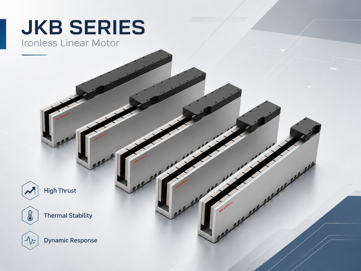 JKB commissioning should consider drive current, guide stiffness, encoder feedback, thermal conditions, and the actual dynamic load profile.
Change one logical parameter group at a time and record the result; otherwise the cause of improvement or deterioration becomes impossible to identify. Standstill should remain quiet and controlled, without unexplained current, audible oscillation, or visible vibration. Do not use extra gain or current to hide preload, guide resistance, feedback noise, gravity load, or structural compliance.
Proceed when: restricted travel, reversal, stopping behavior, current demand, and feedback remain predictable in both directions. The goal is a stable baseline with tuning margin—not production speed yet.
Tuning Sequence for Stability and Settling
Servo tuning should build performance on the stable mechanical and feedback baseline. Choose one repeatable test move with acceleration, useful travel, deceleration, and settling, then keep that profile unchanged while comparing adjustments. Following error matters, but it must be read alongside vibration, current, temperature, settling, and usable cycle time.
Use a staged tuning sequence:
Establish stable feedback behavior before raising position response.
Increase gain only while the frame, fixture, guide, and payload remain mechanically stable.
If oscillation appears everywhere, investigate bandwidth or structural resonance; if it appears at one coordinate, return to geometry, cables, and local mechanics.
Use a targeted filter only after a resonance has been identified and mechanical correction is insufficient or impractical.
Add velocity or acceleration feedforward after the feedback loop is stable; do not use it to conceal changing resistance or unstable feedback.
Payload and fixture resonance often define the practical gain limit. A rigid carriage with a flexible camera bracket, process head, or workholding fixture can behave like two mechanical systems. In those cases, improving fixture or base stiffness may increase usable bandwidth more effectively than another filter or gain change.
Define settling from the process requirement rather than a generic controller number. Position error, residual velocity, vibration, in-position status, image stability, laser-path quality, or dispensing readiness may all matter. Low-vibration JKA-type motion may suit inspection and optical work, while higher-force JKB or iron-core systems place more emphasis on current, frame reaction, and thermal support; the surrounding structure still determines the final result.
Validate the accepted settings with more than one motion condition:
Short point-to-point moves for reversal, small displacement, and settling.
Longer travel for velocity stability, cable behavior, guide consistency, and position-dependent disturbances.
Low speed for friction variation and feedback quality; higher speed for resonance, cable dynamics, voltage capability, and braking response.
Representative payloads and every approved payload condition, using gain schedules only when the controller strategy supports them.
Gradual increases in acceleration, jerk, travel, repetition, and process interaction until the production trajectory is reached.
Proceed when: the same parameter version meets tracking, settling, vibration, current, temperature, and process-quality requirements across the approved operating envelope. Save the payload, test profile, speed, acceleration, filters, feedforward settings, and representative traces with that version.
Thermal, Cable and Full-Cycle Validation
A short stable test does not prove production readiness. Temperature, moving cables, repeated acceleration, process timing, and full-stroke behavior only become clear during a representative duty cycle. This stage changes the question from “Can the axis move?” to “Can the axis repeat the required work without drift or instability?”
Thermal behavior affects the motor, frame, encoder brackets, fixtures, and process position. Compare cold and warm-machine results under a repeatable duty cycle, and record payload, acceleration, cycle and dwell time, ambient condition, cooling state, and process force. Cooling must follow the selected product documentation and continuous operating requirement; one assumption should not be applied across MNK, JKA, JKB, WJM, and WKM.
Full-stroke cable observation belongs in the same validation stage. Watch the carrier near both ends of travel and during reversal. Cables should enter and leave smoothly without twisting, lifting, catching, or applying strong side force. A problem can remain invisible near mid-stroke and appear only at the extreme working position.
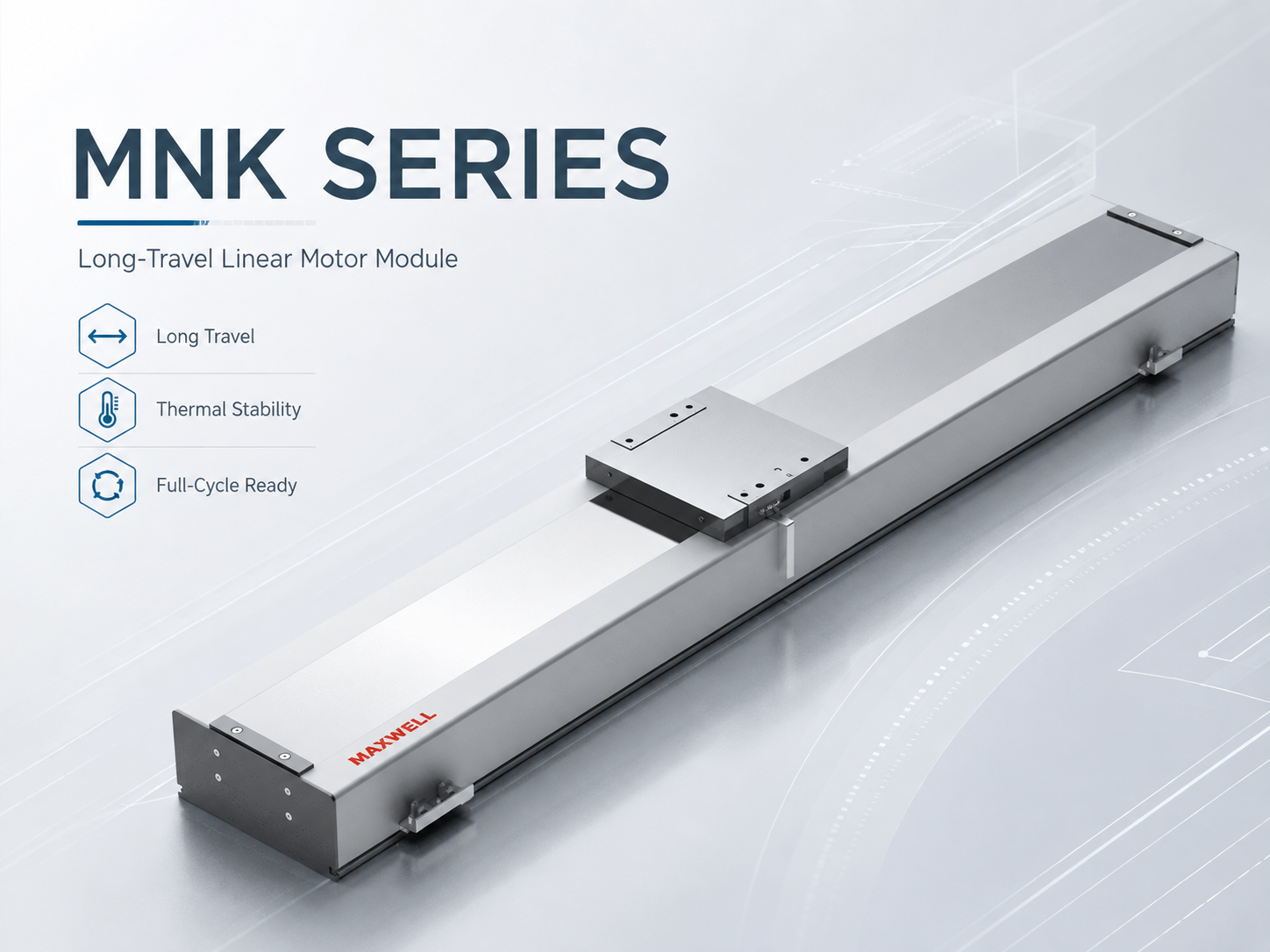 Long-travel validation should include cable-carrier behavior, sensor clearance, thermal stability, and repeated full-cycle motion.
One successful traverse does not validate moving cables or sensors. Repeat enough full-stroke cycles to expose unsuitable bend behavior, weak strain relief, connector loading, or speed-sensitive home, limit, and process triggers. Inspect connector retention again after the endurance run.
Complete-cycle validation should include:
Cold-to-warm repeatability, settling, current, and temperature under the representative duty cycle.
Cable-carrier movement at both ends of travel and through reversal, without twisting, lifting, catching, or strong side force.
Dynamic sensor and process-trigger behavior at operating speed.
Coordinated multi-axis motion; for gantries, synchronization, squareness, homing consistency, and bridge loading at representative acceleration.
Actual process output. A laser motion system, inspection image, dispensing result, or assembly position may reveal vibration or drift that a clean controller trace does not.
Proceed when: temperature reaches an acceptable stable condition, cables and sensors remain reliable, coordinated motion is controlled, and process quality repeats. Persistent high current, rising temperature, or tuning that must be too soft for the required cycle should trigger a review of sizing, cooling, acceleration, payload, mechanical resistance, or structural stiffness.
Acceptance Checklist and Troubleshooting Logic
Acceptance should convert commissioning observations into clear pass conditions. One successful move is not enough. The accepted machine should show stable mechanics, reliable feedback, predictable servo response, complete travel, controlled temperature, reliable sensors, and repeatable process performance. Each result should be tied to the condition under which it was measured.
Project requirements should provide the final limits. Accuracy, repeatability, settling time, cycle time, payload, thermal behavior, and process quality vary between machines. Generic acceptance numbers can create false confidence. Instead, the checklist should compare measured performance with the real equipment specification.
| Check | Acceptable condition | Where to investigate |
|---|---|---|
| Mechanical travel | No contact, binding, abnormal drag, or cable restriction through usable travel | Guide alignment, covers, fixture, base stress, cable forces |
| Motor geometry | Installation remains within approved mechanical requirements through the stroke | Motor alignment, stator position, mounting surface, carriage geometry |
| Feedback direction | Command, physical motion, reported position, and velocity direction agree | Encoder configuration, commutation, controller settings |
| Reference cycle | Homing or reference behavior repeats from approved starting conditions | Sensor location, index event, approach direction, offset, feedback signal |
| Low-speed motion | Stable bidirectional travel without unexpected current or faults | Mechanics, commutation, scaling, cable pull, feedback quality |
| Dynamic response | Required tracking and settling without unstable vibration or excessive effort | Gain, resonance, fixture stiffness, payload, trajectory |
| Thermal behavior | Representative duty cycle remains stable within verified system requirements | Sizing, current demand, cooling, friction, duty cycle |
| Cables and sensors | Reliable through full travel, reversals, and repeated cycles | Bend condition, shielding, strain relief, routing, connectors |
| Production cycle | Complete process repeats without unexplained faults or quality changes | Motion event, current, temperature, timing, process interaction |
Describe the pattern before changing parameters:
Same physical position: inspect guide geometry, cable position, scale condition, covers, sensor brackets, and local structure before making a global tuning change.
Same acceleration or settling event: check resonance, damping, gain, fixture flexibility, inertial demand, and current margin.
Only after warm-up: repeat the same profile from cold to thermal equilibrium and review cooling, structural growth, encoder mounting, and cable behavior.
Intermittent or unclear: preserve alarm history, following-error events, sensor faults, emergency stops, and controller traces as a timeline instead of clearing them without a record.
Linear Motor Commissioning FAQ
| Can one servo parameter set cover several payload conditions? |
| It can, provided the setting retains enough stability and performance margin for every approved payload. Test the lightest, heaviest, and most structurally demanding fixture conditions rather than assuming the heaviest load is automatically the worst case. If the controller supports gain scheduling or application-specific parameter sets, validate each schedule and define clearly when it is allowed to change. |
| How do you decide whether a problem needs retuning or a sizing review? |
| Retuning is appropriate when the motor, drive, thermal condition, and structure have adequate margin but the control response does not yet meet the required tracking or settling behavior. Review sizing when normal production cycles repeatedly approach current limits, temperature does not stabilize acceptably, the required acceleration cannot be reached with margin, or the system must be tuned too softly to meet cycle time. Mechanical resistance, feedback faults, and cooling problems should be ruled out before either conclusion is made. |
| When should the commissioning process be repeated? |
| Repeat the affected commissioning stages after changes to the payload, fixture, guide, encoder, motor or drive configuration, mounting orientation, cable package, cooling arrangement, controller software, safety logic, or production trajectory. A complete restart is not always necessary, but the changed condition and every downstream acceptance result should be revalidated and recorded. |
Build a Repeatable Commissioning Baseline
A successful startup becomes more valuable when it can be reproduced. Save more than the servo parameter file: record payload, installation direction, encoder arrangement, mechanical condition, cable layout, cooling state, software version, and the accepted test trajectory.
For duplicated equipment, retain guide and motor mounting references, encoder alignment, home-sensor arrangement, fixture geometry, and cable routing. When another machine behaves differently, these records show where to investigate before altering servo settings.
The same information also improves early motion-system decisions. An integrated module and a separate mover-and-stator design create different integration responsibilities. For broader architecture planning, the related guide on linear axis design for industrial automation provides context for selecting an axis structure before final commissioning begins.
An engineering review should describe the real application: moving load, stroke, speed, acceleration, cycle time, duty cycle, accuracy, repeatability, installation direction, cooling, environment, encoder interface, drive capacity, controller, and machine-control requirements. Review the motor, guide, encoder, servo drive, structure, and thermal path as one system rather than isolated components.
For an engineering review, prepare: the installed motor series and model, servo drive and controller, encoder type and resolution, moving load or payload, stroke, target speed, acceleration, cycle time or duty cycle, required accuracy or repeatability, installation direction, cooling and environmental conditions. For an existing commissioning problem, also include the alarm history, the position or operating event where the symptom occurs, and available current, following-error, or temperature traces.
Three practical actions help protect the final setup:
Lock the mechanical baseline before performance tuning. Confirm alignment, guide resistance, motor geometry, payload mounting, cables, sensors, and structural stiffness.
Verify feedback before increasing dynamic limits. Confirm direction, scaling, reference behavior, signal quality, and stable low-demand motion.
Accept the complete operating cycle. Validate settling, temperature, full-stroke cables, coordinated motion, sensors, repeatability, and process quality under representative conditions.
When additional sizing, system matching, or commissioning support is required, the most useful request contains actual project inputs and observed behavior rather than only a desired motor model. Those details allow the mechanical load, feedback path, drive capacity, thermal condition, and motion profile to be reviewed as one system.
Send the installed motor and control details, motion profile, payload, stroke, cooling condition, alarm history, and available traces together so the complete system can be reviewed against the same operating cycle. Request a Linear Motor System Review |
A disciplined linear motor commissioning process keeps mechanical, feedback, control, and thermal problems separate long enough to diagnose them correctly. Alignment and feedback come before unrestricted motion, while stable motion comes before aggressive tuning. Full-cycle temperature, cables, sensors, repeatability, and process behavior then determine whether the axis is truly ready for production. This sequence provides a practical acceptance path for MNK, JKA, JKB, WJM, WKM, and other direct-drive systems without using servo settings to hide unresolved machine problems.





















