

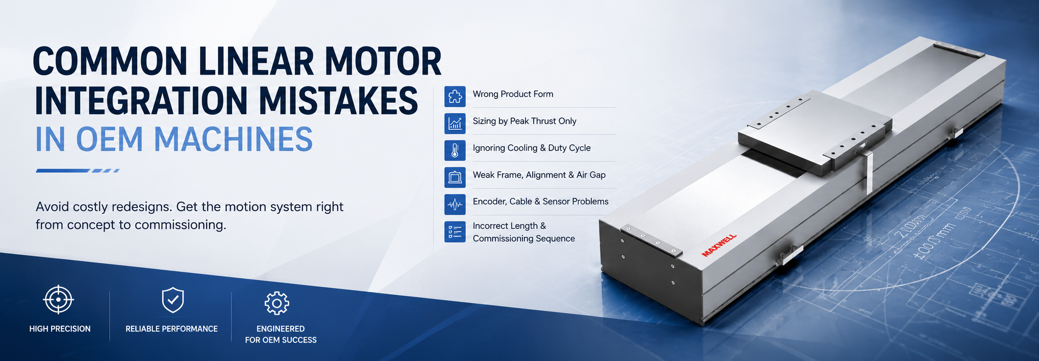
The most costly linear motor integration mistakes rarely begin with a defective motor. They usually start with the wrong product form, peak-thrust-only sizing, underestimated thermal load, a flexible machine frame, noisy feedback, poor cable routing, or an unsafe commissioning sequence. Any one of these problems can reduce the speed, precision, repeatability, and low-wear advantages expected from direct drive.
A reliable OEM design treats the motor, guide, encoder, machine structure, thermal path, cables, sensors, and controller as one motion system. A compact iron core linear motor, for example, may fit a space-limited axis well, but good motor sizing cannot compensate for a weak base, poor feedback installation, insufficient cooling, or the wrong travel geometry.
Practical rule: define the complete motion architecture before confirming the motor model. Product form, force, heat, frame stiffness, feedback, usable travel, cable routing, and control must all support the same operating cycle.
Mistake 1—Choosing the Wrong Product Form
One of the earliest OEM linear motor integration decisions is whether the machine should use a bare motor or a complete linear motor module. A bare motor gives the designer more freedom to select the guide, encoder, base, protection system, cable carrier, and overall machine envelope. That freedom also means the OEM takes responsibility for alignment, sealing, thermal design, sensor placement, cable movement, and final system validation.
The iron core versus ironless choice creates another important branch. Iron core motors are useful when compact force density and strong continuous output matter. Ironless motors eliminate magnetic attraction between the coil and magnet track, which can support smooth force generation and low-vibration motion. Neither structure is automatically better. The correct choice depends on payload, force demand, settling requirements, available space, thermal path, and mechanical construction.
WJM is a practical starting point for compact iron core integration where force density and installation space must stay balanced. It can support inspection, handling, laser positioning, and electronic component assembly automation when the surrounding guide, encoder, frame, and cooling arrangement are designed for the required cycle.
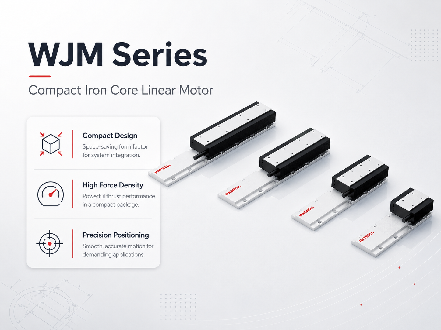
WJM compact iron core motor options for space-conscious precision axes.
What to check before choosing the motor form
Force density versus smooth motion: compact high-force axes may favor iron core construction, while low-vibration precision stages may favor ironless motion.
Bare motor versus module: decide who will engineer the guides, encoder mounting, sealing, lubrication access, cable management, and sensor brackets.
Environment: particles, debris, liquid exposure, maintenance access, and enclosure requirements can change the preferred product form.
Integration responsibility: every mechanical and electrical interface should have a defined drawing, tolerance, inspection method, and owner.
Mistake 2—Sizing by Peak Thrust Only
Peak thrust is important for acceleration, disturbance recovery, and short process-force events, but it does not show how much force the motor must sustain throughout a repeating production cycle. An axis sized only from peak demand may pass an initial motion test and still overheat, derate, or lose repeatability during continuous operation.
Start with the complete moving mass, including the carriage, payload, tooling, cables, hoses, and fixtures. Acceleration force follows the basic relationship force = moving mass × acceleration, but the total requirement must also include friction, gravity, cable-carrier resistance, process force, and a justified engineering allowance.
The next step is a force-versus-time profile for the complete cycle. RMS force provides an important thermal sizing input because it reflects both force level and duration. Peak demand and RMS demand should then be checked separately against the selected motor under the actual cooling condition.
Avoid one common mistake: do not hide missing project data inside a large safety factor. Separate known process force, estimated friction, cable resistance, gravity, and uncertainty so prototype testing can confirm each assumption.
A useful warning sign is an axis that passes isolated moves but heats up, derates, or loses repeatability during repeated cycles. Compare the force-time profile and temperature under the real cycle before simply increasing the safety factor. For the full calculation workflow, review linear motor sizing for payload, acceleration, and cycle time.
For heavier platforms, the high force iron core linear motor range provides a different starting point from WJM. WKM is better aligned with higher-force industrial direct-drive tasks, but higher available thrust also increases the importance of cooling, reaction-force paths, guide capacity, moment loads, and frame stiffness.
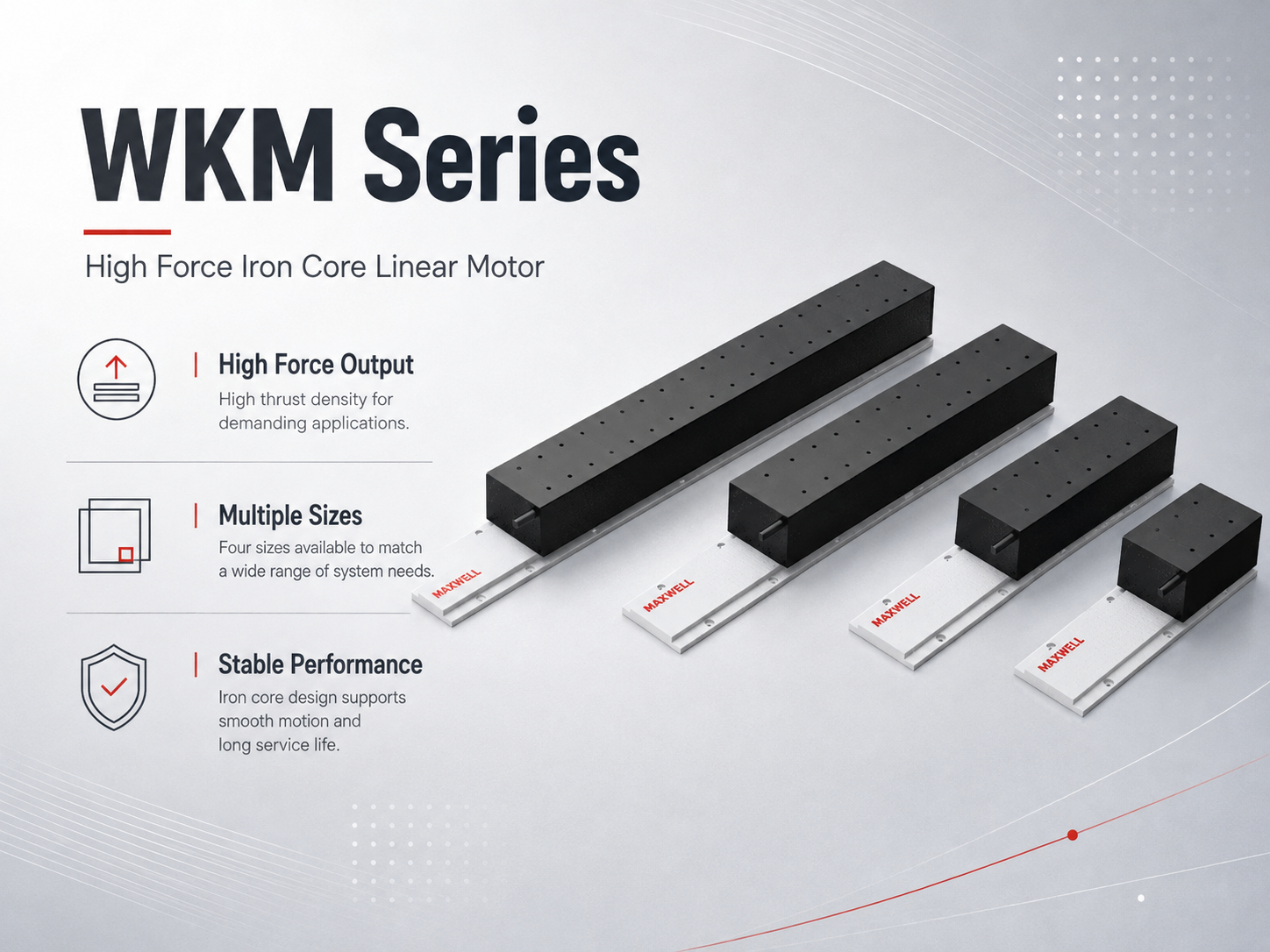
WKM supports higher-force motion concepts when the machine structure and thermal path are designed to use that force.
Mistake 3—Ignoring Cooling and Duty Cycle
Continuous force depends on how effectively motor heat moves into the mounting structure and surrounding environment. The same motor can behave differently on a substantial machined base, a thin plate, or an assembly with poor thermal contact. Ambient temperature, enclosure design, nearby heat sources, airflow, and the production cycle all influence the result.
Duty cycle should not be reduced to one percentage. A cycle with aggressive acceleration, immediate reversal, holding force, and little cooling time may create a much higher thermal burden than another cycle with the same nominal duty percentage. Holding at zero speed can also continue producing heat even though the carriage is stationary.
Cooling mistakes often start when a catalog rating is copied into an OEM calculation without reviewing its thermal assumptions. Define the mounting surface, ambient range, enclosure, airflow, available cooling method, and worst repeating cycle. Thermal expansion should also be considered because it can affect the encoder scale, guide preload, air gap, tooling position, and process alignment.
If accuracy, settling, or force capability changes as the machine warms, treat the temperature trend as an integration clue rather than a tuning problem alone. The detailed linear motor cooling and continuous thrust guide covers the thermal review in more depth.
Validate the warm machine, not only the cold machine
Build the complete force-versus-time profile, including acceleration, process force, holding, return motion, and dwell.
Check both RMS and peak force.
Use the real mounting plate, ambient condition, enclosure, airflow, and cooling method in the thermal review.
Run the prototype through repeated production-like cycles until temperature stabilizes.
Repeat accuracy, settling, and alignment checks after thermal equilibrium.
Mistake 4—Weak Frame, Poor Alignment, or Wrong Air Gap
Direct drive removes belts, screws, and gearboxes from the force path, which also makes structural weaknesses easier to expose. A flexible frame can deflect during acceleration, excite resonance, alter the encoder relationship, and make a correctly sized motor difficult to tune.
Static stiffness is only part of the problem. Bearing spacing, payload center of gravity, cantilevered loads, joint slip, pitch, yaw, roll, and cable-carrier forces all affect dynamic behavior. The complete reaction-force path should be reviewed from the mover through the guide and base into the machine structure.
Air-gap control is equally important. An incorrect or inconsistent air gap can reduce force consistency and increase interference risk. Iron core motors also introduce magnetic attraction during assembly, so fixtures, controlled tightening, clean mounting references, and a documented inspection method are important.
Ironless designs remove magnetic attraction between the coil and track and can support smoother low-vibration motion. The low-vibration ironless linear motor position of JKA is relevant to precision inspection, measurement, and applications where stable settling matters.
That does not eliminate the need for a stiff structure. A smooth motor cannot prevent a flexible carriage from oscillating or a poor guide reference from creating position-dependent error. Mechanical problems should be corrected before aggressive servo tuning is used to mask them.
Useful diagnostic clue: if an unloaded carriage tunes cleanly but settling deteriorates after tooling, payload, or the final cable package is installed, recheck structural compliance, payload center of gravity, guide loading, and cable forces before raising servo gain.
Mechanical checks before servo tuning
Verify base flatness, guide parallelism, carriage freedom, fastener sequence, and mounting reference cleanliness.
Check the specified air gap across the usable stroke.
Inspect cable and hose forces at both travel ends and at the center position.
Confirm payload center of gravity, bearing spacing, and moment loads for the actual installation direction.
Measure repeatability at several positions rather than one convenient location.
Mistake 5—Encoder, Cable, and Sensor Problems
Encoder resolution does not equal complete machine accuracy. Scale mounting, read-head alignment, interpolation quality, structural compliance, thermal expansion, electrical noise, and controller settings all influence the final position result. A finer encoder cannot correct an unstable bracket or flexible mechanical structure.
Cable routing is another common source of intermittent problems. Motor power conductors carry switching current, while encoder and sensor cables carry lower-level signals. Long parallel runs, poor shield termination, weak grounding, crowded cable carriers, and unnecessary cable loops can introduce feedback noise or alarms that appear only while the axis is moving.
Power and feedback separation should continue through the cabinet, moving cable carrier, machine frame, and connector area. Bend radius must remain acceptable across the full travel. Home and limit sensors should also be positioned according to approach speed, controller response, braking behavior, homing direction, and available stopping distance.
When the fault moves with the carriage: if a feedback alarm or sensor fault appears only during motion or at one part of the stroke, inspect cable tension, connector support, shield continuity, power-feedback separation, and sensor-bracket rigidity before treating it as a motor problem.
For more detailed long-stroke routing guidance, review the linear motor cable management and sensor layout guide.
For larger high-dynamic precision stages, the high thrust ironless linear motor range can provide a suitable motor structure. JKB still requires a compatible encoder, stiff guide system, clean feedback routing, correct controller and drive setup, and properly restrained moving cables.
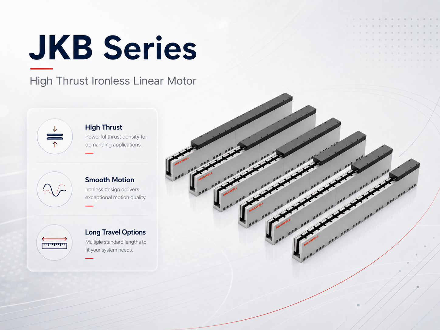
JKB mover and stator options for smooth, high-dynamic precision stage integration.
Mistake 6—Incorrect Stator or Mover Length and Commissioning Sequence
Required motor track length is not automatically equal to working stroke. The axis needs enough active overlap between mover and stator while also allowing space for end margins, sensors, cable movement, mechanical stops, and assembly clearance. Multi-mover systems need additional spacing and independent travel-zone checks.
A longer mover may increase available force, but it also changes moving mass and total installation length. A track that is too short may reduce usable travel or active overlap near the end of the stroke. Final mover and stator length should therefore come from the actual axis drawing rather than a stroke value alone.
Commissioning introduces a separate risk. With no screw, belt, or gearbox mechanically limiting the axis, an incorrect feedback direction or commutation setup can produce rapid uncontrolled motion. Before increasing current or acceleration, verify carriage freedom, cable clearance, limit operation, encoder direction, commutation, feedback polarity, home sequence, and low-speed travel.
Servo tuning should use the final payload and intended cable package because both affect dynamic response. A tune created on an unloaded carriage may behave very differently after tooling, cables, hoses, or the production workpiece are added.
When an OEM project does not want to engineer separate guides, covers, sensor brackets, sealing, and long-stroke cable integration, a sealed linear motor module can reduce the number of machine interfaces that must be designed and validated. MNK provides a complete-module direction for protected, long-travel automation where this integration work is a meaningful part of the project risk.
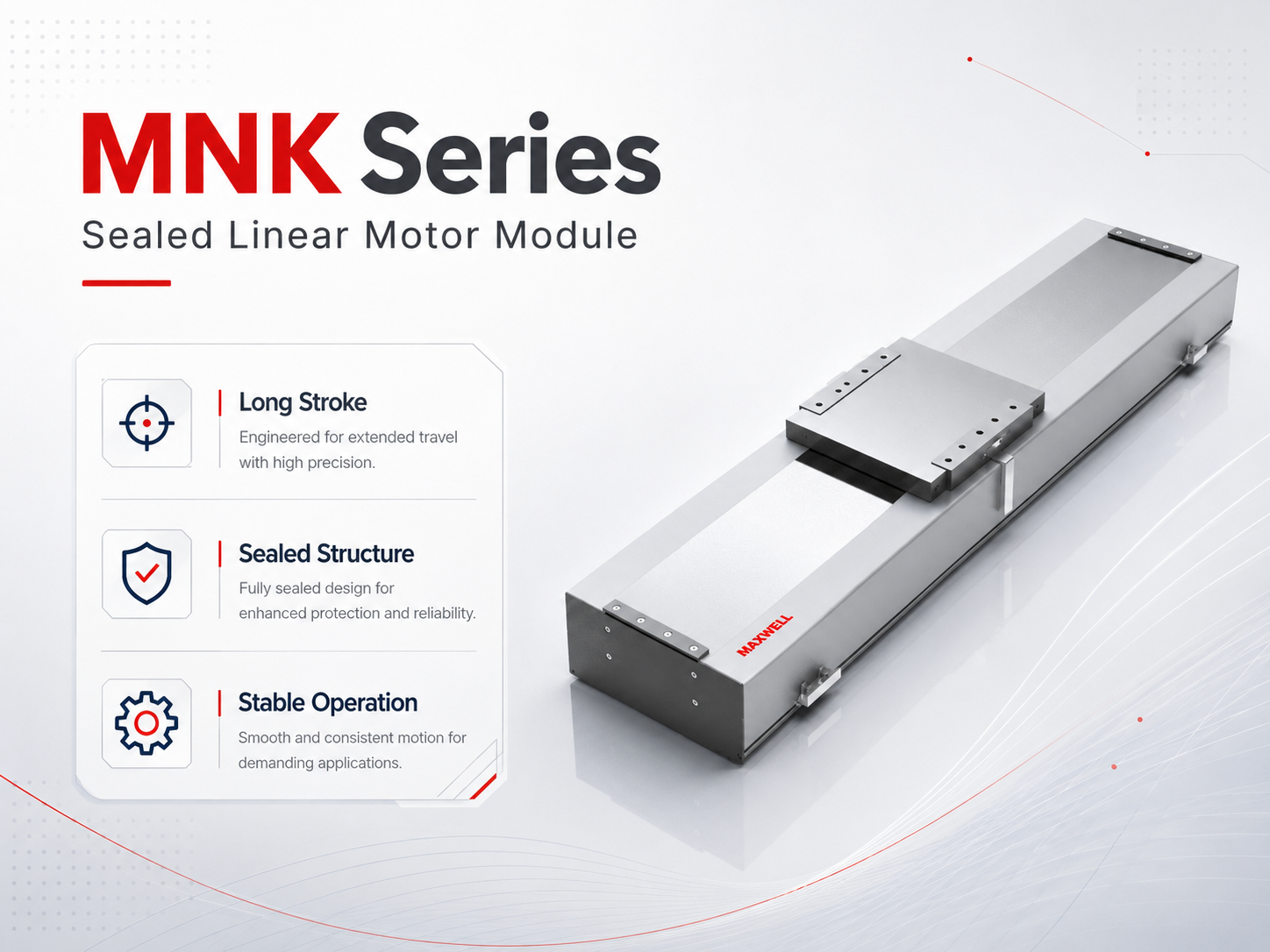
MNK integrates the direct-drive axis into a protected module for long-travel machine layouts.
Where Each Series Fits in the Integration Review
Series selection should begin with the machine requirement rather than a preferred model name. The comparison below shows a useful starting point for each product family and the integration issue that deserves attention before final sizing.
| Series | Useful starting point | Integration point to confirm |
|---|---|---|
| WJM | Compact iron core direct drive where installation space and force density must stay balanced. | Thermal path, magnetic attraction, guide stiffness, air gap, and total installation length. |
| WKM | Higher-force iron core motion for heavier platforms and demanding industrial cycles. | Continuous force, cooling, reaction-force path, moment loads, and frame stiffness. |
| JKA | Ironless low-vibration motion for inspection, measurement, and stable settling. | Encoder, guide, controller, force range, stiffness, and settling target. |
| JKB | Broader-thrust ironless motion for larger or more dynamic precision stages. | Cable restraint, feedback quality, guide stiffness, thermal behavior, and safe stopping. |
| MNK | Protected complete-module direction for long travel and reduced OEM integration scope. | Total envelope, cable carrier, sensor positions, operating environment, and service access. |
The comparison also helps identify when a series is not the right starting point. WJM should not automatically replace WKM when sustained force demand is high. JKA and JKB should not be selected simply because ironless motion is associated with precision. MNK adds the most value when a complete module removes meaningful guide, protection, cable, sensor, or long-travel integration work.
What to Prepare Before Model Selection
A useful linear motor inquiry should describe the operating cycle and machine layout rather than providing only payload and stroke. Missing acceleration, duty cycle, orientation, cooling, or feedback information forces model selection to depend on assumptions that may later require redesign.
| Moving load | Carriage, tooling, fixtures, cables, hoses, payload, and workpiece. |
| Stroke and envelope | Usable travel, available total length, end clearance, and multi-mover spacing if applicable. |
| Motion profile | Target speed, acceleration, deceleration, move distance, dwell, and settling time. |
| Cycle demand | Cycle time, duty cycle, shifts, holding force, and process-force events. |
| Performance target | Required accuracy or repeatability and how the machine will be measured and accepted. |
| Mechanical layout | Installation direction, guide concept, payload center of gravity, and expected moment loads. |
| Cooling and environment | Ambient range, enclosure, airflow, cooling method, particles, debris, and maintenance access. |
| Controls and feedback | Encoder type, controller, servo drive, power supply, cable lengths, and communication requirements. |
A preliminary axis drawing is especially useful because it shows where the motor, guide, encoder, sensors, cable carrier, mechanical stops, and available end clearances must coexist. Problems that are difficult to see in a model list are often obvious in the machine layout.
For a broader view of system architecture and direct-drive configurations, review SAHO’s linear motion solutions for industrial automation.
Common Questions About Linear Motor Integration
| What is the most common linear motor integration mistake? |
| A common mistake is treating motor selection as an isolated force calculation. Motor form, RMS force, cooling, frame stiffness, guides, feedback, cable routing, travel geometry, and controller setup all influence the final axis performance. |
| Why does a correctly sized motor still perform poorly on a weak frame? |
| Motor sizing confirms available force, but it does not guarantee mechanical stability. A weak frame can deflect or resonate during acceleration, reducing usable servo gain, increasing settling time, and creating position error even when the motor has sufficient thrust. |
| When should a bare motor be replaced by a complete linear motor module? |
| A complete module becomes attractive when guide integration, protection, long travel, sensors, cable management, assembly time, or validation effort create significant project risk. A bare motor remains useful when the OEM already has proven mechanical and electrical integration standards and needs greater layout freedom. |
Prevent Integration Problems Before the Hardware Is Fixed
The best time to prevent linear motor integration mistakes is before the axis drawing, motor size, encoder layout, and cable system become difficult to change. SAHO can compare WJM, WKM, JKA, JKB, and MNK against the same operating requirements rather than selecting each component in isolation.
For project matching, prepare the moving load and payload, stroke, target speed, acceleration, cycle time and duty cycle, required accuracy or repeatability, installation direction, cooling and environmental conditions, plus encoder and controller information. A preliminary mechanical drawing is also recommended when available.
For a faster integration review: include the complete motion cycle and available machine envelope rather than only the payload and stroke. This helps identify force, thermal, travel, feedback, and integration risks before hardware selection is finalized.
Send the motion profile, payload, stroke, machine envelope, cooling condition, encoder information, and preliminary axis drawing together so the motor and surrounding integration can be reviewed as one system. Send Your Linear Motor Application Data |





















