

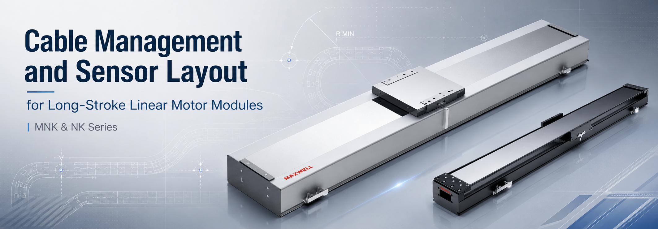
Long-stroke motion stability depends on more than the motor, guideway, and servo tuning. In a real machine, linear motor cable management also affects drag force, settling behavior, signal quality, maintenance access, and the usable motion envelope. A cable carrier that is too small, a bend radius that is too tight, or a limit sensor placed without enough stopping margin can turn a capable linear motor module into an axis that is difficult to commission and expensive to maintain.
Cable routing should therefore be developed with the motion profile rather than added after the mechanical layout is frozen. The same engineering review applies when integrating an MNK sealed linear motor module, an NK stage, or tooling that adds cameras, lighting, pneumatic lines, vacuum, sensors, and process wiring to the moving platform. The objective is not simply to make the cables fit. The moving package must follow the full stroke without adding unpredictable resistance, stressing connectors, disturbing feedback signals, or blocking future service.
Practical design rule: treat the cable carrier, cable bundle, sensors, brackets, and module as one moving system. If any one of those parts changes, repeat the envelope, bend-radius, strain-relief, and sensor-clearance review.
Define the Moving Cable Package
The moving cable package includes every service that follows the carriage. Motor power and encoder feedback are only the starting point. A finished machine may also carry home and limit sensor leads, communication cables, camera cables, illumination power, pneumatic tubes, vacuum lines, valves, process sensors, or tool-specific wiring. The carrier should be sized around this finished package, not around the bare linear motor module shown during the first mechanical layout.
Create a service schedule before selecting the carrier. For each moving item, record the outside diameter, connector size, shielding requirement, minimum dynamic bend radius, continuous-flex requirement, termination location, and whether it must be separated from other services. This simple schedule exposes conflicts early. A cable may be small enough for the carrier but have a connector that cannot pass through the selected opening. A pneumatic tube may fit beside an encoder cable but require a larger bend radius. A future camera or inspection head may add a sensitive signal line that should not share an undivided chamber with motor power.
| Moving service | Record before layout | Why it changes the design |
|---|---|---|
| Motor power | Cable diameter, shield, connector, dynamic bend radius | Sets carrier space, heat considerations, and separation needs |
| Encoder feedback | Feedback type, cable construction, shield method, controller end | Drives noise-control, grounding, and routing decisions |
| Home, limit, and I/O | Sensor type, connector, logic, target location, cable exit | Affects reference consistency, limit response, and service diagnosis |
| Communication or vision | Cable type, moving rating, connector, shielding, allowable length | Can require separate routing from power and careful connector support |
| Air, vacuum, or process lines | Tube diameter, fittings, bend radius, pressure or vacuum requirement | Changes carrier height, divider layout, and torsion risk |
Avoid one common mistake: do not use the cable carrier as storage for spare cable. Extra moving length can cross, twist, rub, or change drag as the carriage reverses. Keep maintenance allowance in a controlled straight service area outside the repeated bending zone.
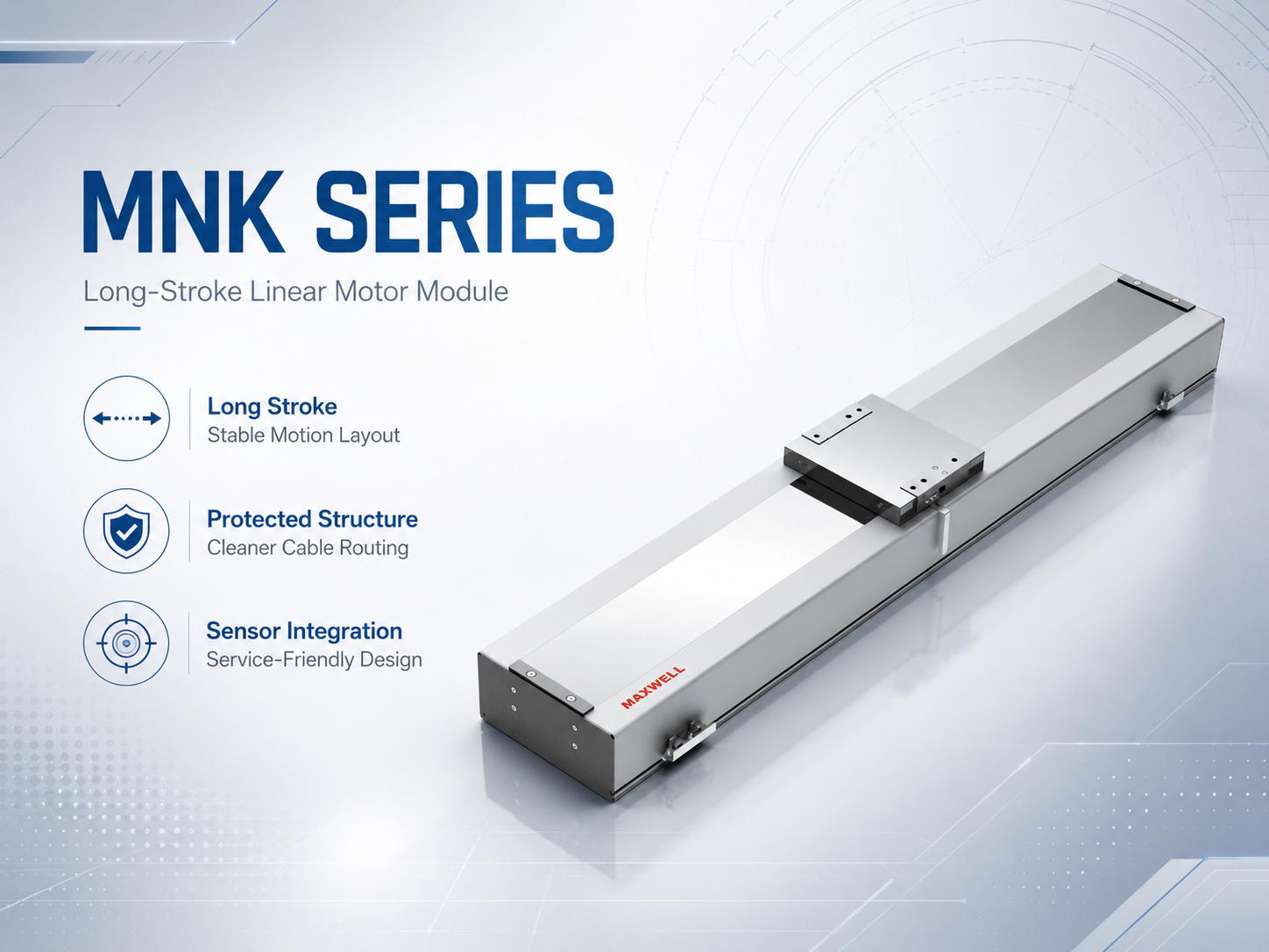
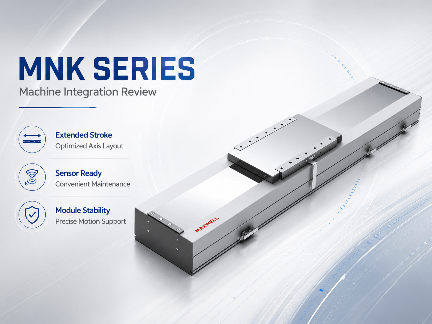
MNK module structure shown as the starting point for external carrier, sensor, and service-routing review.
Cable Carrier Size, Bend Radius and Travel Length
Size the carrier for movement, not static fit
A cable bundle that fits tightly while the machine is stationary can bind once the carrier begins to curve. Cables move relative to one another as the chain bends. If the internal space is too tight, the bundle can press against dividers or neighboring services and create friction that changes with carriage position. Too much free space is also undesirable because cables may cross, twist, or strike the carrier walls during reversal.
A controlled arrangement is easier to inspect. Keep cables in defined lanes where practical, use dividers when power and sensitive signals need separation, and avoid stacking items in a way that lets one cable ride over another. The largest connector should also be considered when planning assembly and replacement. A layout that can only be assembled before the module is installed may create unnecessary downtime later.
Use the largest required dynamic bend radius
The carrier bend radius should start with the most demanding moving service in the package. If one encoder cable, motor cable, communication cable, or tube requires a larger dynamic radius than the others, that item becomes the limiting condition. Static bend data is not a substitute for continuous-flex data. A cable that can be bent tightly during installation is not automatically suitable for thousands or millions of repeated carrier cycles at the same radius.
Check the cable manufacturer's moving-service information rather than assuming that the word “flexible” means cable-carrier rated. The required information should cover the dynamic bend radius, permitted motion type, torsion restrictions, and any guidance on installation inside a carrier. When several services share one carrier, the final radius must be acceptable for all of them.
Plan travel length from the actual fixed point
Long stroke cable routing is influenced by where the carrier is fixed to the machine. A centered fixed point can reduce the moving length in a symmetric layout, while feeding the carrier from one end may require more moving cable and a different support arrangement. The right choice depends on usable stroke, machine space, cabinet location, nearby axes, guard panels, and access for cable replacement.
Length-planning logic: total service length must cover the fixed route, the complete moving loop, and the straight termination allowance. The carrier supplier should confirm the moving-loop length from the real stroke, bend radius, fixed-point position, orientation, and support method.
For long unsupported runs, do not assume that a larger carrier alone solves the problem. The chain may need a guide channel, support surface, gliding arrangement, or another carrier configuration suited to the planned travel. The complete moving envelope should be checked at the left end, right end, and intermediate positions because the widest loop or greatest side clearance does not always occur where the carriage stops.
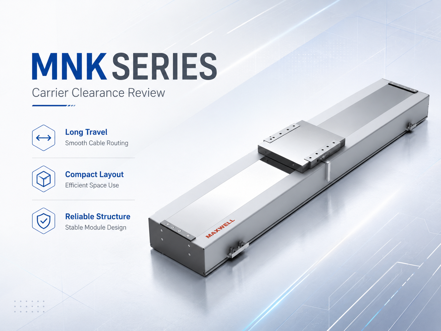
Use the confirmed module drawing to check carrier-side clearance, cable outlet location, and the complete moving envelope.
Fixed End, Moving End and Strain Relief
The cable carrier controls the repeated bend, but it should not carry connector tension. At the fixed end, cables need support before they leave the carrier and continue toward the cabinet or junction point. At the moving end, strain relief should transfer pulling force into a suitable bracket rather than into the motor, encoder, sensor, camera, valve, or process connector.
Clamp the cable jacket without flattening it, and leave a short relaxed straight section between the end of the carrier and the connector. That section accommodates assembly tolerance without moving the repeated bend into the connector exit. If the cable is pulled tight at full stroke, the termination is carrying motion load. If a large loop hangs loose at the opposite end, it can contact the carriage, cover, sensor target, or neighboring hardware. Both conditions should be corrected.
Keep connectors outside the moving curve
A connector is a rigid interruption in an otherwise flexible cable. Placing it inside the curved section concentrates bending beside the connector body and can fatigue conductors, shield terminations, or jacket transitions. Put connectors in straight, supported areas with enough hand space for removal. Where connectors are part of replaceable tooling, define a service position so technicians can disconnect them without moving or partially dismantling the carrier.
Check both ends and the middle of travel
A full-stroke check should include more than the two end positions. The carrier loop may reach its largest envelope or highest side load at an intermediate carriage position. Perform a slow manual or controlled sweep and watch the chain alignment, cable movement, strain-relief loading, connector clearance, and distance to guards or adjacent axes. After the mechanical path is clean, repeat the check under controlled powered motion and then at the intended operating profile.
Position-dependent servo sound, following behavior, or repeated alarms should trigger a mechanical inspection before tuning is changed. If the disturbance always appears in the same part of the stroke, look for local carrier pressure, a twisted cable, a rubbing bracket, or a termination that becomes tight only in that position.
Home, Limit and End-of-Travel Layout
Home, limit, and mechanical-stop functions serve different purposes and should not be treated as one shared boundary. The home sensor establishes a machine reference. Limit sensors define controlled travel boundaries for the motion system. Mechanical stops provide a separate physical containment boundary. Their locations need enough distance between them to support normal homing, controlled stopping, and fault containment without forcing all three functions into the same position.
Place the home target in a repeatable approach zone
A reliable home routine needs a stable sensor target, a defined approach direction, and enough room for the axis to clear and re-enter the target if the controller requires that sequence. A flexible flag or lightly supported bracket can introduce variation even when the sensor itself is functioning correctly. Keep the target rigid, protect its fasteners from accidental movement, and record the approved position after commissioning.
Home placement also needs to make sense for startup. If the carriage can power up on either side of the target, the control logic must still have room to find the correct approach direction without crossing a limit or striking tooling. Check sensor polarity, target width, search direction, and controller behavior together rather than verifying each item separately.
Set travel limit positions from stopping distance
A limit sensor must change state early enough for the axis to stop before mechanical contact. The useful margin is not just the distance from the sensor flag to the hard stop. It must cover deceleration travel, controller and drive reaction travel, positioning or sensor tolerance, and a mechanical reserve. The check should use the worst credible combination of speed, moving load, installation direction, and stop behavior for the machine.
Stopping-margin check: available distance should be greater than the expected stopping distance plus reaction travel and tolerance reserve. Emergency-stop and other safety-related stopping behavior must be validated separately using the machine risk assessment and the actual drive, controller, and safety-system behavior; normal production deceleration should not be used as a substitute.
Illustrative stopping-distance check: for a preliminary review, if an axis is moving at 1.5 m/s and the verified controlled deceleration is 5 m/s², the constant-deceleration distance is v² / (2a) = 0.225 m. If measured controller-and-drive reaction time is 20 ms, the axis travels another 0.030 m before deceleration begins. The preliminary stopping distance is therefore 0.255 m before adding sensor tolerance and mechanical reserve.
This is a calculation example, not an MNK or NK product limit. Final sensor position must use the machine's validated worst-case speed, load, stopping behavior, installation direction, tolerances, and required reserve.
Sensor wiring should remain outside impact zones and away from edges that can cut or pinch the cable. Adjustable brackets need positive locking after setup. A simple witness mark on the bracket and fastener can help maintenance teams see whether a sensor has moved since commissioning. For multi-axis equipment, also check whether an adjacent axis can enter the sensor bracket or cable envelope during service or recovery motion.
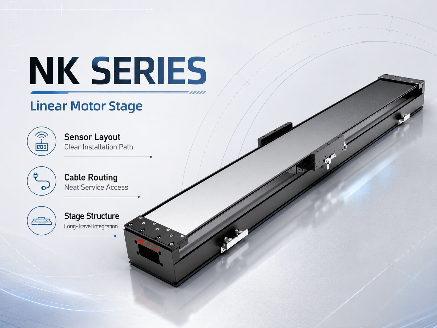
NK stage structure shown for reviewing sensor brackets, cable paths, carriage clearance, and maintenance access.
Separate Power, Encoder and Communication Cables
Encoder cable noise is not only a cabinet problem. Motor power, feedback, communication, and sensor wiring may run beside one another for a large part of a long-stroke axis, so the routing decisions inside the carrier matter. Motor power cables can couple electrical noise into sensitive lines when the paths remain closely parallel, shield continuity is poor, connectors are incorrectly assembled, or excess cable is coiled near feedback wiring.
Where the carrier design allows it, use dividers to keep power and sensitive signals in defined zones. Continue the same routing logic outside the carrier through junction points, trays, and cabinet entry. A carefully separated carrier route loses much of its benefit if motor output and encoder wiring are bundled together again just before the controller. When different cable groups must cross, a near-right-angle crossing generally avoids a long parallel coupling path.
| Observed symptom | Possible routing cause | Useful check |
|---|---|---|
| Position feedback alarms | Encoder cable beside motor power, damaged shield, or poor termination | Inspect separation, shield continuity, connectors, and grounding method |
| Fault appears at one carriage position | Local flex damage, cable pressure, or termination becoming tight | Move slowly through the affected area while monitoring feedback state |
| Intermittent sensor state | Loose connector, noisy shared route, or moving target bracket | Check I/O state, bracket rigidity, connector retention, and cable path |
| Communication dropouts | Unsuitable moving cable, unsupported connector, or routing beside power | Confirm moving rating, shielding, length, connector support, and route |
Use one documented shield and grounding scheme
Shield termination and grounding should follow the drive, encoder, communication, and controller documentation used in the actual machine. Do not change a shield connection simply because a different machine used another method. Connector shells, shield clamps, protective earth, and cabinet bonding work as a system, and inconsistent field changes can create new current paths or remove intended protection.
Troubleshooting is easier when the wiring layout is documented. If an encoder fault appears, the maintenance team should be able to identify the cable route, carrier chamber, fixed and moving terminations, grounding method, and replacement cable specification without reverse-engineering the machine. In inspection equipment and electronic component assembly automation, this matters because an intermittent feedback disturbance can stop a process or create unreliable inspection results even when the mechanics appear normal.
How MNK and NK Structures Change the Layout Review
MNK and NK are both direct-drive module options, but their protective structures create different integration questions. MNK is positioned as a sealed long-travel module, while the NK linear motor stage uses a steel-belt protective structure. Those differences affect the mechanical review around brackets, cable outlets, covers, sensor access, and maintenance space. They do not remove the need for an external moving-service plan.
Do not select the carrier mounting side from a generic product photo. Use the selected model drawing and the real machine layout. Confirm the cable outlet, moving platform interface, cover clearance, nearby tooling, sensor bracket location, and the direction in which technicians will access the axis. A clean-looking routing path on one side may become unusable once a guard panel, camera bracket, or adjacent axis is added.
| Layout question | MNK review | NK review |
|---|---|---|
| Protective structure | Check how the sealed module outline affects external brackets and service access | Keep carrier and sensor hardware clear of the steel-belt protection and its service area |
| Cable outlet | Align carrier entry with the confirmed model outlet and installation side | Check outlet direction against carriage tooling, guards, and adjacent structure |
| Sensor mounting | Use accessible external brackets without interfering with the protected module structure | Keep targets and wiring clear of the steel belt and the moving carriage envelope |
| Maintenance access | Leave room to inspect external carrier hardware and terminations along the protected module | Avoid blocking cover-related access with carrier brackets or cable junctions |
| Best comparison basis | Machine environment, long-travel layout, usable space, outlet position, and service path | Stage structure, cover clearance, tooling envelope, outlet position, and sensor access |
Long-stroke integration should be reviewed as a complete machine envelope, including carrier, tooling, sensors, guards, and service space.
Installation and Linear Motor Cable Management Inspection Checklist
A reliable installation is easier to achieve when the same checklist is used at three stages: drawing review, machine assembly, and commissioning. The drawing review catches space and routing conflicts before hardware is released. Assembly checks confirm that the real parts match the drawing. Commissioning proves that the carrier, sensors, and signals remain stable through the actual motion profile.
List every moving service. Record cable and tube diameters, connector sizes, dynamic bend radii, shielding, flex requirements, and termination points.
Confirm the full motion envelope. Include the carrier loop, strain-relief brackets, sensor targets, guards, adjacent axes, tooling, and maintenance hand space.
Choose the carrier fixed point deliberately. Compare centered and end-fed layouts against stroke, cabinet location, service length, and support requirements.
Check the largest dynamic bend radius. Base the carrier radius on the most demanding cable or tube in the moving package.
Protect both terminations. Keep connectors out of the bend and provide strain relief at both fixed and moving ends.
Separate power and feedback paths. Continue the separation through junctions, trays, cabinet entry, and the final controller connections.
Define home and limit logic. Verify approach direction, target width, sensor polarity, stopping margin, mechanical-stop clearance, and restart behavior.
Perform a slow full-stroke sweep. Watch for chain climbing, cable crossing, cover contact, changing tension, sensor interference, and connector movement.
Run the planned motion profile. Observe feedback alarms, sensor state, servo behavior, unusual sound, cable movement, and any position-dependent disturbance.
Document the approved installation. Record clamp positions, sensor locations, carrier data, replacement cable specifications, and service inspection points.
What to inspect after the machine starts running
Inspection frequency should reflect the actual cycle rate, speed, acceleration, stroke, and operating environment. During service, look for jacket polishing, dust from rubbing, loose dividers, changed clamp positions, connector movement, a carrier that no longer tracks centrally, or sensor brackets that have shifted. These signs are useful because moving-cable problems often develop gradually before they become electrical faults.
When a fault is intermittent, compare it with carriage position and motion direction. A fault that appears at the same point in the stroke suggests a local cable or carrier problem. A fault that appears only during acceleration may point toward cable movement, electrical coupling, or a connector that is sensitive to vibration. A sensor fault after maintenance may be caused by a bracket or target position rather than the sensor electronics themselves. Using the machine position as part of the diagnostic record makes troubleshooting faster.
For broader axis planning, review linear motion solutions for industrial automation. Cable routing should be considered together with payload, stroke, machine structure, feedback, controller selection, installation direction, and service access rather than treated as an isolated accessory decision.
Common Questions About Linear Motor Cable Management
| How should cable carrier length be planned for a long-stroke module? |
| Plan carrier length from the real usable stroke, fixed-point position, bend radius, support method, and both termination routes. A centered fixed point can reduce moving length in some symmetric layouts, but the final length should be confirmed from the actual machine drawing and the carrier supplier's calculation method. |
| Why is the dynamic bend radius important? |
| Repeated bending below the specified dynamic radius increases stress in conductors, shields, jackets, and tubes. Use the largest required dynamic bend radius among all moving services as the starting point for carrier selection, and confirm that each cable is rated for repeated carrier motion. |
| Where should home and travel limit sensors be installed? |
| The home sensor needs a rigid target, repeatable approach direction, and enough room for the controller's homing sequence. Travel limit sensors should change state early enough to provide the verified stopping distance plus reaction travel, tolerance, and mechanical reserve before the axis can contact its physical stop. |
| How can encoder cable noise be reduced on a long-stroke axis? |
| Keep encoder feedback separated from motor power where the layout allows, avoid unnecessary long parallel routes, use the specified moving-service cable, and follow the encoder, drive, and controller documentation for shielding and grounding. Continue the same separation through junctions and cabinet entry. |
| What cable information should be provided for an MNK or NK layout review? |
| List every service that moves with the axis. For each cable or tube, provide the outside diameter, connector size, dynamic bend radius, shielding requirement, continuous-flex requirement, preferred outlet side, and termination location. A machine drawing showing usable stroke, carrier fixed point, tooling, guards, and cabinet direction makes the review more useful. |
Final Checks Before Releasing the Axis
A long-stroke module should not be released for production based only on successful point-to-point motion. Verify that the carrier moves consistently through the entire stroke, every cable remains within its dynamic bend requirement, connectors stay unloaded, home and limit sensors have clear functional margins, and feedback wiring follows one documented routing and grounding plan. Those checks reduce the chance that a mechanical routing issue is later misdiagnosed as a servo, encoder, or module problem.
For MNK or NK model and layout review, submit the moving load or payload, required stroke, target speed, acceleration, cycle time or duty cycle, required accuracy or repeatability, installation direction, cooling and operating environment, plus encoder and controller information. For every cable, tube, camera, vacuum line, communication line, or other service that moves with the axis, include the outside diameter, connector size, dynamic bend radius, shielding requirement, continuous-flex requirement, preferred outlet side, and termination location when available. A machine drawing showing usable stroke, carrier fixed point, tooling position, nearby guards, and cabinet direction helps identify routing conflicts before the final layout is released.
For an engineering layout review, send your motion profile, payload, stroke, cable and tube requirements, installation direction, and controller information together. Send Your Linear Motor Application Data |





















