

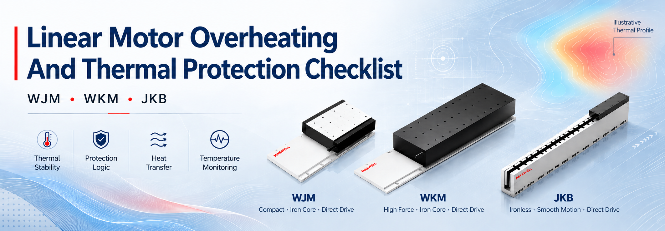
When a linear motor runs hotter than expected, the motor itself is only one part of the investigation. RMS current, duty cycle, mounting contact, cooling performance, enclosure temperature, mechanical resistance, and servo behavior all affect the final temperature. A motor can therefore overheat even when its peak force rating looks sufficient.
A useful thermal review starts by separating two conditions: is the axis generating more heat than expected, or is the machine removing less heat than before? That distinction makes troubleshooting faster and prevents unnecessary changes to motor size or protection limits.
For compact direct-drive equipment, a compact iron core linear motor may fit the available space, but reliable continuous operation still depends on the complete thermal path and protection strategy.
Core engineering rule: peak current creates short bursts of heat, while RMS current and effective heat removal determine the long-term temperature trend. Both conditions need to be checked before an axis is approved for production.
Why a Linear Motor Can Run Hot Even When Peak Force Looks Sufficient
The coil assembly is normally the main electrical heat source. Copper loss can be approximated by P = I2R, which means a moderate increase in sustained current can produce a much larger increase in heating. Winding resistance also increases as the coil becomes hotter, reducing the remaining thermal margin.
Peak thrust alone does not describe this condition. Acceleration, deceleration, process force, vertical holding force, friction, and settling corrections all contribute to the current profile. Repeated short moves may also leave too little time for heat to leave the motor between cycles.
Use the complete cycle, not one demanding move
For a simplified motion cycle, RMS current can be estimated as:
IRMS = √[(I12t1 + I22t2 + …) / (t1 + t2 + …)]
Because current is squared, high-current portions have a disproportionate effect on heating. The calculation is useful for preliminary review, but the final decision should still be based on measured drive current and temperature during a representative production cycle.
Mechanical and control problems can also increase thermal demand without any change to the selected motor. Misaligned guides, excessive preload, contaminated bearings, cable-carrier drag, vertical counterbalance problems, or continuous servo correction can all increase current. These faults often appear to be a cooling problem even though the real cause is elsewhere in the axis.
Compare continuous force, peak force, RMS current, and the real duty cycle.
Include acceleration, deceleration, holding, process force, and settling in the current profile.
Check guide resistance, cable drag, and vertical loading before assuming the coil is the problem.
Look at standstill current for oscillation or repeated position correction.
How the Heat Path Affects Linear Motor Temperature
Heat has to move from the coil assembly into the mounting structure and then into the surrounding air or cooling circuit. A restriction close to the motor can dominate the entire thermal path. A large machine frame provides little benefit if a thin adapter plate, poor surface contact, coating, burr, debris, or uneven clamping restricts heat transfer first.
Confirm the intended heat-transfer surface from the motor drawing. The mating plate should provide stable contact without rocking or local gaps, and it should remain flat after machining and assembly. Fasteners should follow the specified pattern and tightening method. Thermal interface material should only be used when the mechanical design and motor documentation allow it.
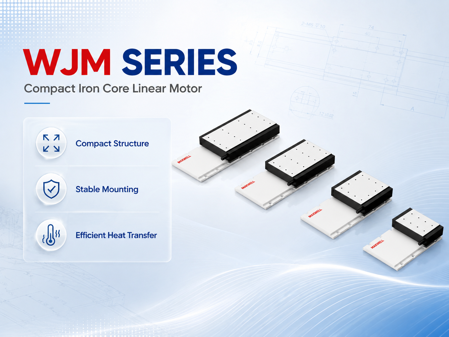
WJM compact iron core motor assemblies require a stable mounting path for both force transmission and heat transfer.
Confirm the designated mounting and heat-transfer surfaces.
Check flatness, cleanliness, burr removal, coating, and complete contact.
Review plate thickness, stiffness, heat-spreading area, and connection to the frame.
Inspect the fastener pattern and tightening condition.
Measure the real enclosed temperature near the motor and encoder, not only the room temperature.
When Cooling Performance Becomes the Limiting Factor
Cooling method selection is a separate design topic, but thermal protection still depends on confirming that the intended cooling path is working during production. Natural convection, forced air, and liquid cooling fail in different ways, so the protection strategy should reflect the system actually used on the machine.
For a more detailed comparison of natural, air, and liquid cooling and their effect on continuous output, see the linear motor cooling and continuous thrust guide.
| Cooling condition | What to verify |
|---|---|
| Natural convection | Enclosure temperature, heat spreading, installation orientation, and nearby heat sources. |
| Forced air | Fan operation, filter loading, airflow direction, dead zones, contamination, and exhaust recirculation. |
| Liquid cooling | Flow, inlet temperature, pressure, coolant condition, hose routing, blockage, leaks, and condensation risk. |
In a forced-air system, the fan rating alone does not prove that useful airflow reaches the motor. Filters, narrow ducts, cable bundles, covers, and recirculated exhaust can create stagnant areas. Approved airflow visualization, anemometer measurements, or surface-temperature mapping can help identify these problems during prototype testing.
Liquid-cooled systems need the same level of verification. Flow direction, hose routing, fittings, bend radius, and manifold balance all affect performance. In a multi-axis machine, a clear return line does not prove that every parallel branch receives the required coolant flow.
Coolant temperature also needs attention. Very cold coolant may improve heat removal, but surfaces below the local dew point can collect condensation around connectors, encoder components, or nearby machine structures.

Higher-force WKM applications should be reviewed against sustained load, real duty cycle, and the cooling available in the machine.
Do not approve cooling by touch. Surface temperature cannot show internal coil temperature, local hot spots, or a slowly rising production-cycle trend. Use logged sensor and process data.
Temperature Sensors and Thermal Protection
A temperature sensor only protects the motor when its signal is correctly understood by the drive or controller. Sensor type, wiring, input configuration, scaling, warning limits, trip limits, and reset behavior all need to match the selected motor and control system.
Some temperature devices provide a changing measurement, while others operate as threshold devices. They require different controller inputs and diagnostic methods. The sensor circuit should be identified from the connector and approved documentation rather than assumed from wire color.
Use more than one level of protection
A practical system can use an early warning before temperature reaches a shutdown condition, followed by a controlled stop when continued operation is no longer acceptable. Drive-level or equivalent protection should prevent sustained operation beyond the approved thermal limit.
Exact alarm and trip values should come from the selected motor, sensor, drive configuration, and machine risk assessment. Generic temperature limits are not reliable because winding limits and sensor locations vary between products.
Confirm sensor type, connector pins, cable continuity, shielding, and input compatibility.
Check whether the displayed temperature is plausible before motion begins.
Verify engineering-unit scaling and detection of an open or short sensor circuit.
Test warning, controlled-stop, and drive-trip responses separately.
Set reset behavior according to the motor documentation, controller strategy, and machine risk assessment.
Record the actual fault source so maintenance can distinguish motor temperature from a cooling-system failure.
When active cooling is required, the cooling system should also be monitored. Depending on the machine, useful signals may include fan operation, filter differential pressure, coolant flow, inlet and outlet temperature, reservoir level, or chiller status. High-load operation should not continue when the required cooling path is unavailable.
Commissioning: Establishing a Reliable Thermal Baseline
A thermal test should reproduce the real production cycle rather than a convenient no-load move. Use the intended payload, speed, acceleration, dwell time, process force, vertical holding condition, and enclosure environment. If several recipes are used, test the one expected to create the highest thermal demand.
Begin with mechanical and feedback checks at reduced current and speed. Once motion direction, encoder feedback, limits, guide resistance, and basic servo behavior are correct, increase the cycle in controlled steps. This makes it easier to detect excessive friction or unstable tuning before a long thermal run.
Log enough information to explain the trend
At minimum, record time, motor temperature, drive current, cycle state, ambient temperature, and alarm status. Add fan and filter condition for air-cooled systems. For liquid-cooled systems, record inlet temperature, outlet temperature, and verified flow information. Mounting-plate and frame temperatures can also help identify a restricted heat path.
Continue the test until the project acceptance condition is reached or a defined stop criterion occurs. A short plateau during an idle period does not prove that the system has reached thermal equilibrium. Look at repeated cycle peaks and the long-term baseline. If the baseline continues to rise, heat is still accumulating.
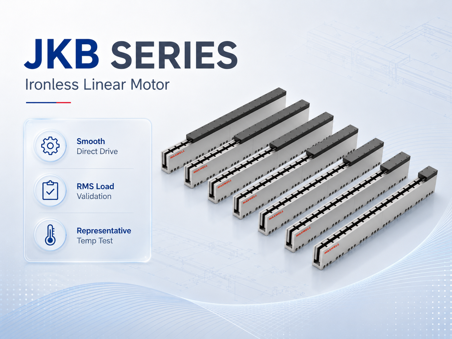
JKB ironless motor applications still need a representative temperature test at the intended RMS load.
Baseline: record ambient, coolant, motor, mounting plate, and drive conditions before the run.
Reduced-load run: confirm motion, sensor plausibility, current behavior, and cooling operation.
Representative cycle: use the real payload and complete production timing.
Thermal trend: watch temperature peaks, baseline drift, RMS current, and cooling behavior together.
Protection test: verify alarms and stop logic using an approved test or simulation method.
Acceptance record: save the recipe, software version, load, environment, data, and conclusion.
Leave margin for real production variation. Filter loading, seasonal ambient changes, payload differences, and longer production runs can create harsher conditions than a clean prototype test. A design that only passes under ideal conditions does not have a robust operating window.
What Current and Temperature Trends Reveal About Overheating
When a machine that previously ran normally begins to run hotter, the commissioning data becomes especially useful. Comparing temperature and current together can quickly narrow the investigation.
| What you see | Where to look first |
|---|---|
| Temperature rises but RMS current is similar | Check airflow or coolant flow, filter condition, mounting contact, enclosure temperature, and other changes in the heat-transfer path. |
| Temperature and current both rise | Check guide resistance, lubrication, payload, process force, vertical loading, cable drag, and servo stability. |
| Temperature reading changes suddenly | Inspect the sensor circuit, connector, scaling, cooling loss, current surge, and possible mechanical obstruction. |
Gradual deterioration is common. Filters clog, fan bearings wear, coolant channels collect deposits, hoses kink, connectors loosen, and guide resistance can increase as lubrication or alignment deteriorates. A useful maintenance check therefore looks beyond the motor itself.
Cooling path: fans, filters, ducts, coolant flow, hoses, fittings, manifolds, and chiller alarms.
Thermal contact: fasteners, mounting damage, contamination, and recent mechanical work.
Motion resistance: guides, lubrication, alignment, seals, cable carrier, and payload.
Electrical demand: current traces, standstill current, servo gains, and settling behavior.
Sensor condition: plausibility against ambient or an independent measurement where appropriate.
Production conditions: recipe changes, shorter dwell times, longer shifts, and warmer enclosure air.
A sudden temperature jump deserves a different response. Stop the axis safely, preserve the fault record, and inspect cooling loss, current surge, sensor wiring, and mechanical obstruction. Repeatedly clearing the alarm before identifying the cause removes useful diagnostic evidence.
After maintenance, repeat the relevant part of the commissioning test. Replacing a fan or clearing a coolant line does not by itself prove that the original thermal performance has returned. Compare the new trend with the baseline before releasing the machine back to full production.
WJM, WKM and JKB: What Changes in the Thermal Review?
Motor structure changes which mechanical and thermal details deserve the most attention. The comparison below is not a substitute for model-specific sizing data; continuous current, temperature limits, sensor type, and cooling requirements should always be confirmed for the selected motor.
| Series | Typical design context | Thermal review focus |
|---|---|---|
| WJM | Compact iron core direct drive for precision equipment with limited installation space. | Mounting contact, plate heat spreading, continuous duty, enclosed temperature, and mechanical loading around the iron-core structure. |
| WKM | Higher-force iron core motion for heavier stages and demanding production cycles. | RMS current, sustained process force, cooling capacity, mounting stiffness, and cooling-system supervision. |
| JKB | Ironless direct drive for smooth precision motion without iron-core magnetic attraction. | Coil heat path, high-acceleration RMS demand, temperature protection, and thermal drift around the precision structure. |
A high force iron core linear motor may be appropriate when sustained and peak-force requirements exceed a compact platform's practical range. Higher available force does not remove the need for complete-cycle RMS review and thermal validation under the intended production schedule.
A high thrust ironless linear motor supports smooth direct-drive motion without the magnetic attraction associated with an iron-core structure. The coil still produces copper loss, so sustained acceleration and compact installation require careful temperature validation.
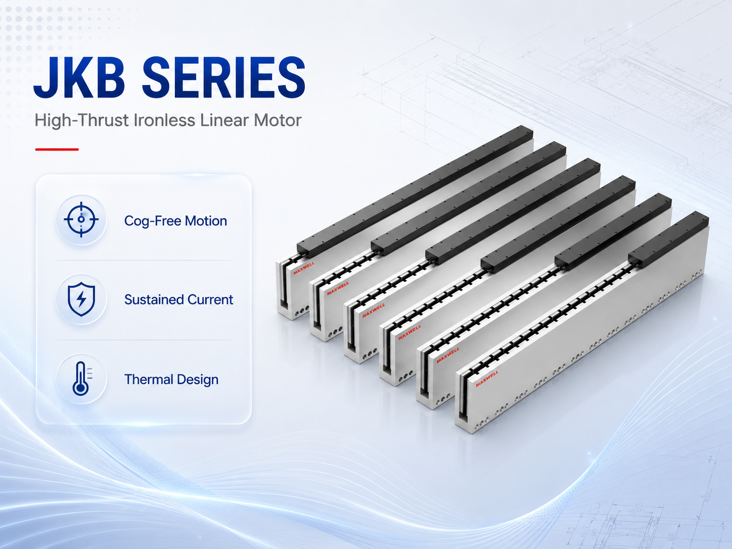
JKB high-thrust ironless configurations combine smooth direct drive with thermal performance that still depends on sustained current and the machine heat path.
In a laser motion system, temperature can affect more than motor protection. Changes in the motor and surrounding structure may influence encoder relationships, optical alignment, positioning stability, and settling behavior. Thermal acceptance should therefore include positioning or process stability after the axis reaches its normal operating temperature.
Thermal performance also depends on the complete linear axis design for industrial automation. Guide arrangement, encoder mounting, cable routing, enclosure design, frame stiffness, and cooling hardware can all change the final operating margin.
Common Questions About Linear Motor Thermal Protection
| Why can a correctly sized linear motor still overheat? |
| A motor can overheat even when peak force is sufficient because long-term temperature depends on RMS current, duty cycle, heat transfer, enclosure temperature, mechanical resistance, and servo behavior. Compare current and temperature trends with the commissioning baseline before concluding that the motor itself is undersized. |
| How can I tell whether overheating is caused by higher load or poorer cooling? |
| If temperature rises while RMS current remains close to the previous value, investigate the heat-transfer path, airflow or coolant flow, mounting contact, and enclosure temperature first. If both current and temperature rise, check mechanical resistance, payload, process force, cable drag, vertical loading, and servo stability. |
| What should be checked in a linear motor thermal protection circuit? |
| Check the temperature sensor type, connector pins, input compatibility, scaling, warning response, trip response, sensor-fault detection, and reset behavior. If active cooling is required, also monitor the relevant fan, coolant flow, inlet temperature, reservoir, or chiller condition. |
| How long should a commissioning thermal test run? |
| Run the representative production cycle until the defined acceptance condition is reached or a stop criterion occurs. Do not approve the axis from one short reading or a temporary plateau during idle time. Look at repeated cycle peaks and the long-term baseline to confirm that heat accumulation has stabilized. |
| When should the motor or cooling system be resized? |
| Review the design when representative testing exceeds the approved temperature limit, leaves too little operating margin, or requires current above the permitted continuous capability. Improve cooling when heat removal is the restriction; revisit motor sizing when complete-cycle RMS force demand remains too high. |
What to Prepare Before Final Motor Selection
A useful engineering review should describe the complete axis rather than only a preferred motor series. Provide the moving load or payload, stroke, target speed, acceleration, cycle time, and duty cycle. Also include the installation direction, required accuracy or repeatability, cooling and environmental conditions, encoder information, and controller or drive information.
With these inputs, continuous force, peak demand, thermal behavior, mechanical integration, and protection requirements can be reviewed together instead of being treated as separate problems.
Calculate complete-cycle RMS demand and identify the production recipe with the highest thermal load.
Define the heat path, cooling supervision, temperature-sensor logic, and thermal acceptance conditions.
Run a logged production-cycle test and keep the result as the maintenance baseline.
For an engineering review, send your motion profile, payload, installation direction, duty cycle, cooling conditions, and controller information together. Send Your Linear Motor Application Data |





















