

Low-speed vibration does not automatically mean a linear motor has a cogging problem. The practical way to reduce cogging force and motion ripple is to identify which part of the disturbance actually comes from the motor before changing hardware or servo settings. Similar symptoms can come from energized force ripple, guide friction, encoder error, cable drag, structural resonance, thermal movement, or unstable feedback. Separating these effects first leads to a clearer engineering decision and prevents an expensive motor change from solving the wrong problem.
Start with the symptom, not the motor label: a repeating low-speed error is evidence, but not yet a diagnosis. Position, direction, speed, motor current, temperature, and process state usually reveal where the disturbance begins.
When testing confirms that magnetic disturbance is a meaningful part of the error budget, a low-vibration ironless linear motor becomes relevant. That structural choice cannot correct a distorted guide, noisy encoder, flexible frame, or changing cable load. Those sources require their own corrections before motor architecture becomes the main solution.
Consider a scanning axis that shows a small velocity wave every time it crosses the same part of the stroke. The motor may be the source, but a guide high point, encoder interpolation pattern, or cable-chain bend can produce the same clue. A useful investigation follows that one symptom through matched forward and reverse moves, a second speed, and a warmed-up production cycle. The result—not the first visual impression—decides whether the correction belongs in the motor, mechanics, feedback, structure, or cable path.
What Causes Cogging Force and Motion Ripple?
Cogging force is position dependent. In an iron-core linear motor, interaction between permanent magnets and ferromagnetic motor geometry can create preferred magnetic positions along the travel path. A periodic force can therefore exist even when commanded motor current is relatively small.
Force ripple describes a wider group of operating effects. Once the motor produces thrust, variations in magnetic-field distribution, commutation, electrical angle, phase balance, force constant, or current regulation can create small changes in output force. Low classical cogging and low energized force ripple are related goals, but they are not the same measurement.
Mechanical friction can create a similar velocity trace. Guide preload, lubrication, seals, contamination, mounting distortion, and local bearing resistance all influence low-speed motion. Feedback can create another false lead: a repeating encoder error may cause the controller to command a correction that was never required by the true mechanical position. The resulting current then converts a measurement error into real movement.
A useful diagnostic model is:
Measured motion disturbance ≈ electromagnetic disturbance + friction + feedback error + structural response + external force
This is not an exact calculation because several terms can interact. Its purpose is to organize the investigation. Instead of asking whether the motor has ripple, ask which term dominates the observed error under the actual operating condition.
Read the waveform before changing hardware
A disturbance that repeats at the same physical position can be magnetic, but position repeatability alone is not proof. Encoder-scale behavior, local guide resistance, drag-chain geometry, mounting distortion, and contamination can all create a pattern tied to travel position.
Similar travel wavelength at different speeds: a spatial source becomes more likely.
Similar vibration frequency at different speeds: structural resonance or control oscillation deserves attention.
Strong forward/reverse difference: friction, preload, cable force, or mechanical hysteresis becomes more likely.
Error grows with acceleration or current: energized force ripple, commutation, structural deflection, or process loading should be checked.
Error changes after warm-up: thermal geometry, lubrication, cable stiffness, or temperature-dependent feedback behavior may be involved.
More than one source can exist at the same time. A small electromagnetic disturbance may become obvious only because the structure amplifies it. Another axis may appear magnetically rough even though guide friction or cable force dominates the motor-current trace.
Matched forward and reverse strokes after thermal stabilization are especially useful because friction changes direction. A directional current offset or a local rise without additional acceleration points toward preload, lubrication, cable resistance, or another external load. Keep speed, payload, path, and process condition comparable so the result reflects the machine rather than a changed test.
Mechanical Alignment, Air Gap and Guide Quality
A direct-drive motor sends force straight into the moving structure, so poor guide geometry or motor alignment appears directly in the servo load. The mover and magnet track must maintain the motor-specific air gap shown in the approved drawing through usable travel. Checking only the center is not enough: accumulated pitch, yaw, height, or rail error can change guide loading and magnetic geometry farther along the stroke.
A repeatable position error can still be mechanical
A local high point beneath a guide rail, uneven fastener loading, contamination, a damaged raceway, or changing preload can create resistance at nearly the same position on every stroke. That repeatability can easily be mistaken for magnetic periodicity. Rail mounting surfaces deserve particular attention because debris or uneven tightening can pull the rail or base plate away from its intended geometry.
A useful mechanical review includes:
Guide straightness and parallel relationship through usable travel.
Carriage preload, lubrication, contamination, and local resistance.
Mover-to-magnet-track relationship across the stroke.
Rail support, plate flatness, fastening sequence, and mounting stress.
Clearance around covers, cable chains, bellows, and process hardware.
Preload improves rigidity, but excessive or uneven preload raises friction and can create stick-slip or changing current at low speed. Lubrication condition changes both breakaway force and steady resistance. A single high-force travel region should therefore be inspected mechanically before servo gains are changed.
Measure the point where the process happens
The motor applies force at one location, the encoder measures position at another, and the camera, laser head, probe, optic, sensor, or workpiece may sit farther away. Those offsets matter when the moving structure has finite stiffness. A tall payload creates a larger acceleration moment than a compact payload of the same mass, so the carriage can appear stable while the working point experiences additional pitch or yaw.
Guides, base structures, magnet tracks, encoder scales, tooling plates, lubrication, and cables may also follow different thermal paths. Record cold, partially warmed, and thermally stable conditions. A large temperature-related change should be investigated before permanent compensation is created.
Encoder Signal Quality and Servo Compensation
Feedback check: the servo reacts to measured position, so a smaller displayed increment does not automatically mean smoother motion. Resolution, accuracy, interpolation, readhead alignment, scale mounting, signal noise, grounding, latency, and controller processing all matter.
Resolution, accuracy, and interpolation are different
Resolution describes how finely the system reports position. Accuracy describes how closely reported position follows true position over a defined travel. Interpolation error can create a shorter repeating deviation within the encoder signal cycle. At low speed, velocity estimation relies on very small changes in measured position, so a repeating feedback error can appear as real speed variation. The servo responds with current and converts that error into physical motion.
Compare disturbance wavelength with known encoder periodicity where the required data is available. Inspect readhead alignment, scale condition, moving cables, connectors, routing relative to motor conductors, shielding, grounding, and available controller diagnostics. A cable fault can appear only when the drag chain reaches one part of its bend, creating an apparently position-dependent error that has no magnetic cause.
Tune only after the machine and feedback are stable
Higher servo gain does not improve measurement quality. If the controller is reacting to feedback noise or interpolation error, more aggressive tuning can make the motor respond more strongly to the same false information. Standstill jitter without commanded movement can indicate noisy feedback, excessive loop gain, structural resonance, or another unstable condition.
Feed-forward, friction compensation, filtering, and position-dependent mapping can improve motion when they target a known residual error. A position-related disturbance that remains stable across repeated strokes may be a reasonable compensation candidate. Changing guide friction, moving cable force, loose structure, or temperature-sensitive geometry is not.
Frame Rigidity, Cable Drag and Process Disturbance
Direct drive removes belts, screws, couplings, and gearboxes from the thrust path, but the moving structure still has finite stiffness. A flexible frame can store energy and release it during settling. A small periodic force may then produce a much larger visible position disturbance near a structural mode, so vibration amplitude alone does not reveal the size of the original motor disturbance.
Cables, pneumatic tubes, vacuum or coolant hoses, optical fibers, bellows, seals, web tension, and process contact all resist movement. Drag-chain geometry, temperature, hose pressure, bundle size, and bend radius make that load change across the stroke. If the disturbance appears only after production utilities or tooling are connected, review those forces before blaming the motor.
Laser equipment is a useful example. A moving head can carry optical cables, cooling lines, extraction hoses, electrical wiring, and protective components at the same time. A laser motion system should therefore be evaluated as one moving assembly rather than as a motor and encoder in isolation.
Settling time often exposes stored energy in the frame, payload, or tooling. Acceleration and jerk influence how strongly those modes are excited, so a smoother command can shorten the total cycle when reduced settling outweighs a small increase in travel time. Judge the result under representative scanning, indexing, contour, process-dwell, and return conditions rather than one extremely slow demonstration.
Match the Symptom to the Most Useful Response
Start with the production symptom, then change one meaningful condition at a time. This keeps the investigation practical while connecting each result to a corrective direction.
| Observed symptom | Possible source | How to verify and respond |
|---|---|---|
| Ripple repeats at fixed travel positions | Magnetic periodicity, encoder error, guide condition, cable geometry | Plot repeated strokes against physical position, then compare encoder periodicity, guide condition, and cable geometry. Review motor structure or mapped compensation only if a stable electromagnetic pattern remains. |
| Amplitude grows with acceleration or motor current | Force ripple, commutation, structural deflection, process loading | Compare matched moves at different force demand. Review commutation and current regulation if the pattern follows motor effort; review stiffness and process loading if the working point moves more than the carriage. |
| Forward and reverse traces differ | Friction, preload, cable force, mechanical hysteresis | Run matched bidirectional strokes. A large directional offset points toward alignment, preload, lubrication, seals, or cable resistance rather than a motor replacement. |
| Travel wavelength remains similar as speed changes | Position-related disturbance | Compare the physical distance between peaks and check it against motor, encoder, guide, and cable geometry before assigning the pattern to cogging. |
| Vibration frequency stays similar at different speeds | Structural resonance or control oscillation | Review frequency response, tooling stiffness, jerk, and loop settings. Reduce the excitation or strengthen the force path before relying on a filter. |
| Error appears only in one travel region | Cable chain, guide defect, encoder contamination, mounting distortion | Inspect the matching physical area for rail distortion, debris, scale contamination, drag-chain loading, or interference and correct the local source. |
| Current rises without commanded acceleration | Guide drag, cable load, hose force, process resistance | Compare current, position, direction, and process state. Correct guide, hose, cable, bellows, or contact force if the extra current follows an external load. |
| Error changes after warm-up | Thermal geometry, lubrication, cable stiffness | Repeat the same baseline from cold to stable temperature. Review thermal geometry, lubrication, cable stiffness, and feedback mounting before creating permanent compensation. |
| Standstill jitter without commanded movement | Feedback noise, excessive gain, resonance | Review the feedback signal, grounding, structure, and servo bandwidth. Improve signal integrity or stability before increasing gain. |
The table is not a request to perform nine unrelated tests. Begin with the condition that reproduces the production problem, record position, velocity, current, direction, speed, and temperature, then change the one variable most likely to separate the competing explanations. Return to the same baseline after every meaningful correction.
If the disturbance changes when the guide, feedback path, cable arrangement, structure, or process load changes, correct that physical source. If a stable electromagnetic pattern remains under matched conditions, low-cogging motor structure and repeatable compensation become technically relevant rather than simply desirable catalogue features.
Buying decision: if the dominant source is guide, feedback, cable, structure, or process force, correct that source before buying another motor. If a meaningful electromagnetic disturbance remains, motor structure and exact model selection can enter the shortlist.
When an Ironless Linear Motor Is the Right Direction
Iron-core motors use ferromagnetic material around the windings to concentrate magnetic flux. This supports strong force density, but the magnetic structure introduces a conventional cogging mechanism and normal magnetic attraction that must be included in guide and frame design.
Ironless motors remove the iron teeth from the moving coil structure, so the classical tooth-to-magnet cogging mechanism is absent. Energized force ripple, encoder error, structural vibration, external forces, thermal change, and servo instability can still remain. For a broader structural comparison, review ironless linear motor vs iron core linear motor after the disturbance source has been identified.
JKA and JKB are both ironless motor families. JKA is relevant for smooth precision direct drive when verified force, stroke, envelope, and thermal conditions fit one exact configuration. JKB extends the ironless selection path across a wider range, including higher-thrust configurations, but it is not the automatic next size above every JKA model.
Compare the exact continuous thrust, peak thrust, mover mass, mover and stator dimensions, usable stroke, installation envelope, thermal condition, drive compatibility, and feedback architecture. An iron-core WJM or WKM direction can remain appropriate when force density, industrial loading, thermal management, or installation space carries more weight than the measured cogging contribution.
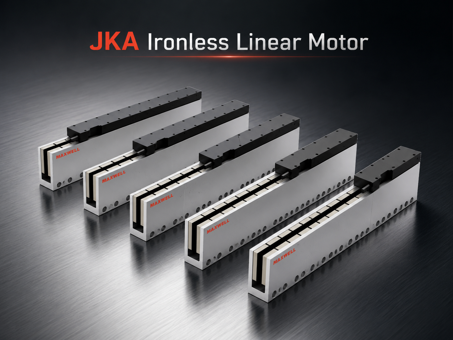
JKA Ironless Linear Motor
A cog-free ironless direction to compare for scanning, inspection, optical positioning, measurement, and other low-disturbance motion tasks.
| View JKA Series |
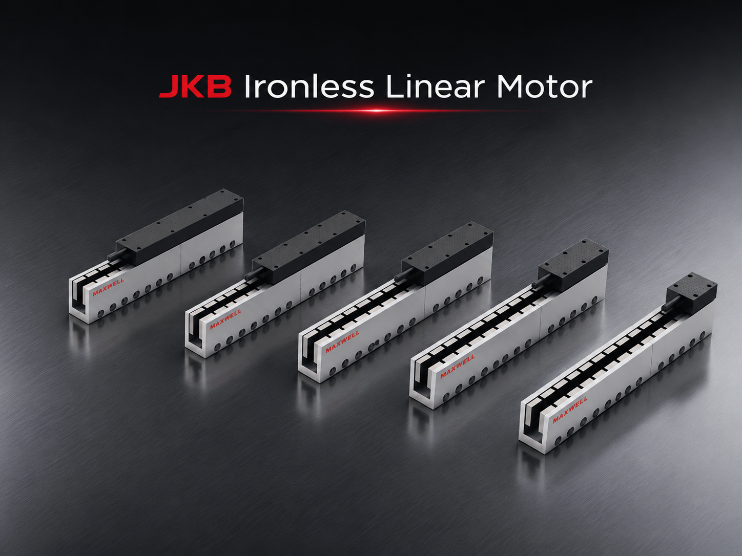
JKB Ironless Linear Motor
A wider-range ironless direction to compare when smooth motion remains important and the required force moves beyond a suitable JKA configuration.
| View JKB Series |
Diagnosis narrows the motor direction; it does not complete sizing. Moving mass, acceleration, process force, gravity where applicable, cable resistance, duty cycle, force at speed, cooling, available space, guide loading, and drive compatibility still determine whether one exact configuration fits. Use the SAHO guide on linear motor sizing for payload, acceleration and cycle time for the complete peak-force, continuous-demand, force-speed, thermal, and integration review.
Frequently Asked Questions
How can I tell cogging force from guide friction?
Compare matched forward and reverse strokes and plot current and motion error against physical position. A large directional offset or local rise in current without additional acceleration makes guide friction, preload, cable load, or another external resistance more likely. A stable spatial pattern still requires encoder and guide checks before it is assigned to the motor.
Can an ironless linear motor eliminate all motion ripple?
No. Ironless construction removes the classical cogging mechanism associated with iron teeth interacting with the magnet track. Feedback error, energized force ripple, structural vibration, thermal change, cable loading, process force, and servo behavior can still affect the complete axis.
When should JKA or JKB be considered?
Consider an ironless JKA or JKB direction when low-disturbance motion matters to the process and electromagnetic disturbance remains meaningful after guide, feedback, cable, structure, and process checks. Compare exact configurations rather than choosing only by family name; required force, stroke, mover mass, space, thermal conditions, duty cycle, feedback, and drive compatibility still control final selection.
What to Prepare Before the Final Engineering Review
A useful review should include evidence that helps separate the disturbance source, followed by the machine information required to compare a suitable motor configuration.
Send one compact evidence package:
Commanded and actual position, velocity, current, and following-error traces where available.
Matched forward/reverse runs, a second speed or force condition, and the physical location of repeating peaks.
Cold and thermally stable results, with guide, encoder, cable, hose, tooling, and process condition noted.
Complete moving mass, payload variation, tooling, and important center-of-gravity offset.
Usable stroke, target speed, acceleration, deceleration, cycle time, settling requirement, and duty pattern.
Installation direction, available space, cooling, environment, accuracy target, encoder, controller, servo drive, and known process forces.
These inputs allow JKA, JKB, an iron-core alternative, guide structure, feedback, and control to be reviewed as one motion system. They also prevent a motor change from being used to solve a disturbance that actually originates elsewhere in the machine.
When the measured limitation remains electromagnetic and the engineering objective is to reduce cogging force without sacrificing required thrust, thermal margin, accuracy, repeatability, or production-cycle performance, send both the motion evidence and the complete operating profile for model-level confirmation.
| Send Motion Data for Engineering Review |





















