

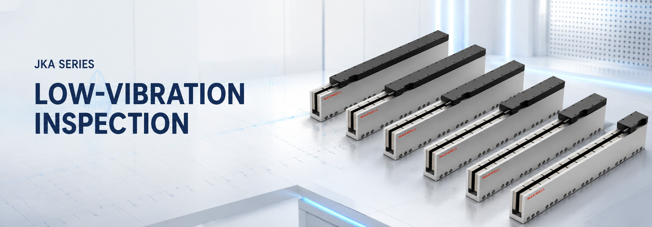
In inspection equipment, maximum axis speed is only one part of throughput. A low vibration linear motor for inspection systems must also maintain smooth velocity during scanning, stop without disturbing the sensor, and settle inside the measurement window before data capture begins. In optical inspection, metrology, wafer handling, and laser measurement, stable motion and repeatable settling can matter more than the highest catalogue speed.
SAHO's JKA ironless linear motor range is relevant when cog-free force generation and low-disturbance direct drive support the inspection process. The motor still has to work inside a complete motion loop: guide quality, encoder feedback, frame stiffness, cable forces, thermal behavior, and servo settings all influence the finished axis.
Where JKA fits: think of JKA as the force-producing heart of the inspection axis, not as a finished stage by itself. Its cog-free ironless design can support smooth motion, but the result the camera or sensor actually sees still depends on the guideways, carriage and frame, encoder feedback, servo drive and controller, cable behavior, and the way heat is managed through the duty cycle.
A better selection question: instead of asking which motor is fastest, ask which motion system reaches the inspection window quickly and can stay there repeatably. Peak speed helps only when the sensor, mechanics, feedback, and control loop remain stable while measurement is taking place.
Why Inspection Systems Need Low-Vibration Motion
An inspection axis usually alternates between movement and measurement. During movement, the stage must follow the commanded profile smoothly. During measurement, residual motion must fall below the process limit before the camera, probe, laser, or optical sensor begins collecting valid data.
This makes settling time a production metric, not only a servo statistic. A faster move can reduce travel time but increase the delay before the next usable reading. A slightly gentler acceleration or deceleration profile can produce a shorter total cycle when it prevents overshoot and structural ringing.
Smooth velocity matters just as much during continuous scanning. Line-scan cameras, laser triangulation sensors, and continuous measurement heads depend on consistent position increments. If velocity ripple changes sample spacing, the output can show banding, scale distortion, or inconsistent feature density even when final positioning repeatability looks acceptable.
The Measurement Window Comes Before the Motor Choice
Start with the condition that releases the measurement trigger. That condition may be a position-error band, velocity threshold, acceleration threshold, or a combination held for a defined dwell period. Without that definition, “fast settling” cannot be compared meaningfully across motors, stages, or servo settings.
Point inspection: confirm the allowed position error and dwell time before exposure.
Continuous scanning: define allowable velocity ripple and sample-spacing variation.
Probe measurement: include contact force, approach speed, and structural recovery before the reading is accepted.
Laser processing or measurement: separate path accuracy and synchronization requirements from final-position repeatability.
The disturbance source also needs to be identified. Cogging, guide friction, cable drag, floor vibration, fan excitation, frame resonance, encoder error, and servo noise create different symptoms and require different corrections. If the problem is specifically low-speed periodic force ripple, the separate guide on reducing cogging force in precision linear motion is the better troubleshooting reference.
How JKA Ironless Motion Supports Inspection Performance
JKA uses an ironless linear motor structure. With no iron core in the moving coil assembly, the conventional tooth-to-magnet cogging mechanism and normal magnetic attraction associated with iron-core structures are removed. That is useful when the process depends on smooth low-speed motion, consistent scan velocity, or short settling after a move.
Direct drive also removes a screw, coupling, gearbox, or timing belt from the force path. The control loop therefore does not have to compensate for transmission backlash or periodic screw error from those components. This does not make the finished axis vibration-free: current-loop ripple, encoder interpolation error, guide defects, cable forces, structural modes, and thermal drift can still limit the inspection result.
If the design decision is still between ironless and iron-core motor architecture, use the dedicated ironless linear motor vs iron core linear motor comparison. For this inspection-focused selection, the more useful question is whether JKA fits the required force, motion profile, packaging, and settling target.
Peak Force Is Only Half the Sizing Picture
Peak-force screening begins with the total moving mass and commanded acceleration. A useful engineering estimate is peak force ≈ moving mass × acceleration + friction + cable force + process force. Add a documented allowance for modeling uncertainty rather than selecting an arbitrarily oversized motor.
Continuous-force demand depends on the complete inspection cycle rather than the hardest instant. For a multi-segment move, a useful engineering estimate is FRMS ≈ √[Σ(Fi² × ti) / T], where Fi is the force in each motion segment, ti is that segment's duration, and T is the total cycle time. Repeated acceleration, scanning, holding, settling, and return moves can create a thermal demand that is not visible from peak thrust alone.
Oversizing deserves caution in precision equipment. A larger motor can add moving mass, require a larger drive, alter structural modes, and make the axis harder to package. The preferred range is the one that meets peak-force and thermal requirements while preserving the intended mechanical bandwidth and installation envelope.
JKA1 vs JKA2: Series Data and Selection Logic
The JKA product range includes JKA1 and JKA2 families. JKA1 covers the lower listed force range, while JKA2 extends the upper range and offers more listed rotor lengths. The final choice still depends on the complete application because force, stroke arrangement, duty cycle, drive capability, installation space, and heat removal interact.
| Specification | JKA1 | JKA2 |
|---|---|---|
| Continuous thrust | 50–300 N | 77–1003 N |
| Peak thrust | 200–1200 N | 309–4012 N |
| Listed rotor lengths | 61 / 121 / 181 / 241 / 301 / 361 mm | 61 / 121 / 181 / 301 / 361 / 481 / 541 / 601 / 661 / 721 / 781 mm |
| Listed stator lengths | 120 / 180 / 300 mm | 120 / 180 / 300 mm |
These figures describe series coverage, not guaranteed output in every installation. Continuous capability depends on heat removal, ambient conditions, duty cycle, and mounting. Usable stroke also depends on the motor arrangement and mechanical layout, so stator length should not be read as the finished-axis travel.
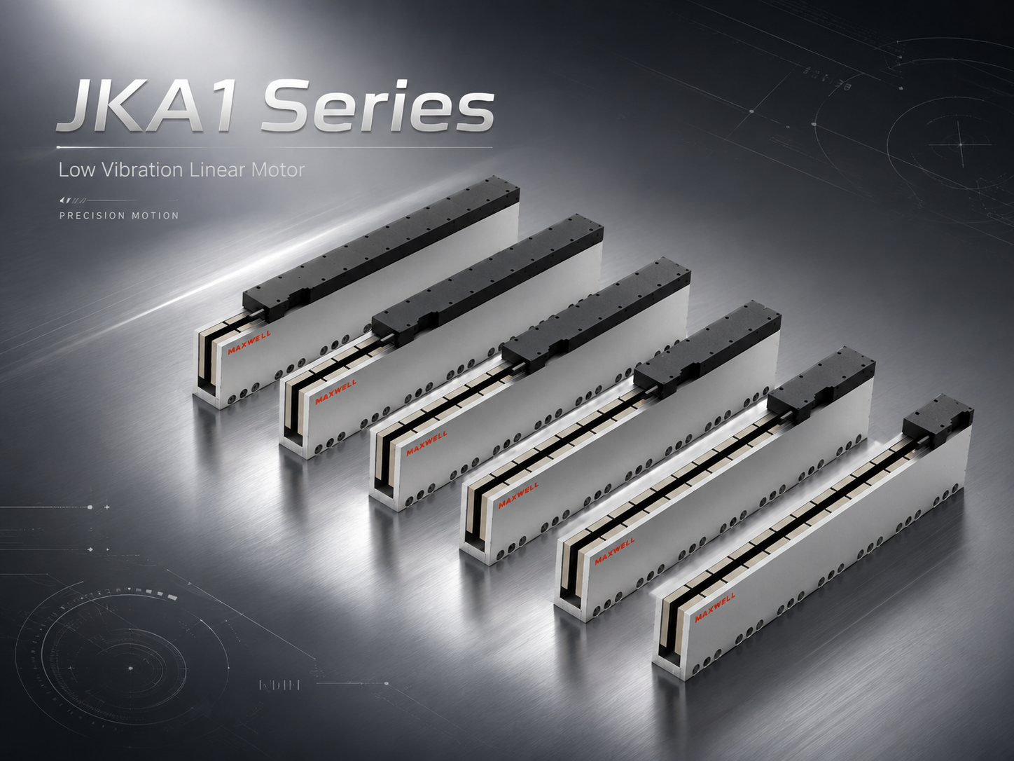
SAHO JKA1 ironless linear motor for precision inspection and smooth direct-drive motion.
JKA1 is the logical starting range when the calculated peak and RMS force remain within its listed force range and the available lengths fit the mechanism. JKA2 becomes relevant when higher continuous or peak force is needed. Its broader rotor-length list can also support different force and packaging combinations, but the exact motor arrangement should still be confirmed against the real motion cycle.
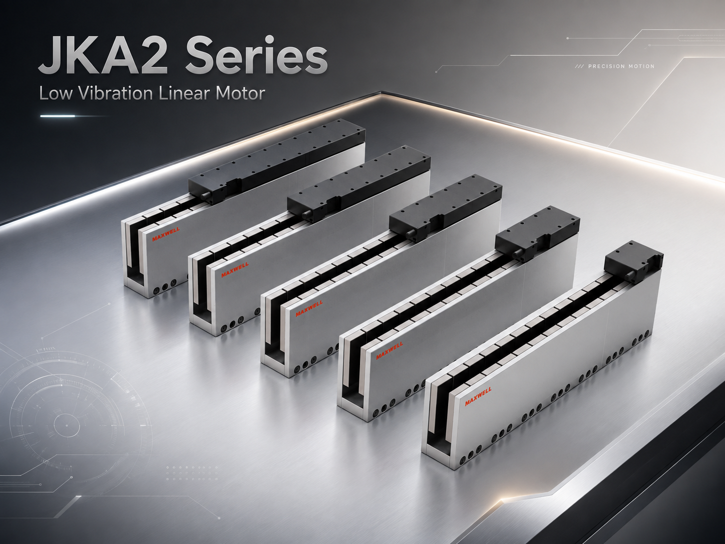
SAHO JKA2 ironless linear motor for higher-force precision motion requirements.
Do not stop the comparison at the highest number in each range. A sound shortlist checks peak force during acceleration, RMS force over the cycle, expected heat removal, drive-current capability, available motor length, cable routing, and the effect of moving mass. This keeps the selection tied to the inspection cycle instead of one catalogue value.
Why Settling Depends on More Than the Motor
Motor force creates motion, but feedback and mechanics determine how precisely the controller can observe and correct it. Encoder resolution should not be mistaken for finished-system repeatability. Scale accuracy, interpolation error, signal quality, mounting, thermal expansion, and the distance between the scale and measurement point all affect the result.
A high-resolution encoder can expose small motion errors, but it can also reveal noise that weak mechanics cannot control. Excessive filtering may make a feedback trace look calmer while adding phase delay. Encoder performance, drive bandwidth, and servo filters should be reviewed as one control system rather than as independent specifications.
Guide behavior appears directly in the force loop
Guide preload improves stiffness, but excessive preload can increase friction and heat. Poor rail alignment can create position-dependent drag that the controller repeatedly corrects. During a slow scan, that correction may appear as velocity ripple even when the motor itself has no conventional cogging.
Moment loading deserves equal attention. An offset camera, microscope, probe, or cable carrier can pitch, yaw, or roll the carriage during acceleration. Guide spacing and carriage geometry should therefore be selected from the real center of mass and external moments, not payload mass alone.
Frame stiffness sets the settling ceiling
A controller cannot remove every flexible mode from a light or poorly supported frame. If a move excites a low-frequency structural resonance, increasing servo gain may make the oscillation worse. The machine base, sensor bracket, payload plate, and cable supports should form a short, rigid load path before aggressive tuning is attempted.
Settling tests should use the actual payload and a representative cable arrangement. Record commanded position, encoder position, following error, velocity, and the measurement-trigger signal. The acceptance result should state the error band, dwell window, move distance, payload, and motion profile so that two designs can be compared under the same condition.
Measure baseline vibration with the axis enabled but stationary.
Run the representative production move, not only the longest or fastest move.
Calculate settling from motion completion to the defined measurement window.
Repeat at several positions to expose cable drag and guide variation across the stroke.
Repeat after thermal stabilization to identify temperature-related drift.
Servo tuning should follow mechanical verification. Feedforward can reduce following error, while notch filters can address identified resonances. Each gain or filter change should be validated against both point-to-point settling and scan-velocity stability because improving one metric can degrade the other.
The Best JKA Choice Depends on How the Machine Measures
JKA is most relevant when smooth direct drive and low disturbance matter more than squeezing the highest possible force density into the axis. What counts as a good result depends on how the machine measures. A camera that stops and exposes, a line-scan sensor that acquires continuously, and a probe that touches the part all put different demands on motion quality, so “precision” by itself is too vague to guide the choice.
| Inspection mode | Primary motion question | Evidence to request during evaluation |
|---|---|---|
| Stop-and-capture optical inspection | How quickly can the axis enter and remain inside the measurement window? | Settling trace, error band, dwell time, payload, move distance, acceleration profile, and repeat count. |
| Continuous line-scan or laser scan | Can the axis hold the required velocity quality while the sensor is acquiring data? | Velocity ripple, trigger synchronization, scan direction, reversal behavior, acceleration zones, and encoder data. |
| Probe or contact measurement | How does the structure recover after approach or contact force? | Approach speed, contact force, structural recovery, following error, fixture stiffness, and acceptance dwell. |
| Wafer or thermally sensitive metrology | Does motion quality remain stable after the machine reaches operating temperature? | Warm-up profile, duty cycle, ambient range, heat path, scale material, cable routing, and measured drift. |
For broader machine-level comparisons, use the dedicated guide on linear motor stages vs ball screw actuators for inspection. Semiconductor and laser equipment that needs an integrated stage rather than motor components is covered separately in SAHO's linear motor stage applications for semiconductor and laser equipment. Compact in-line inspection connected with handling or assembly can also be reviewed in the electronic component assembly automation application page.
When to Compare JKA with JKB or an NK Stage
The correct comparison starts with product structure. JKA is a component-level ironless motor range for smooth precision motion within its listed force range. JKB is also ironless, but it provides broader force coverage when the inspection platform, acceleration requirement, or RMS demand moves beyond a suitable JKA combination.
The JKB high-thrust ironless linear motor range deserves review when more continuous force, peak acceleration force, or platform scale is required while low-cogging direct drive remains important. Cooling, drive current, installation size, and added moving mass should be checked at the same time.
NK solves a different integration problem. SAHO presents NK as a steel-belt-protected linear motor stage with an integrated guide structure. It is the more natural comparison when the machine builder wants a complete protected guided module instead of designing the guide, carriage, protection, and motor integration around a JKA component set.
| Option | Stronger reason to consider it | Main engineering responsibility |
|---|---|---|
| JKA | Cog-free component motor for smooth inspection motion within the listed force range. | Design the guide, frame, feedback, protection, cabling, and thermal path. |
| JKB | Broader high-force ironless coverage for larger or more dynamic precision platforms. | Verify force, current, cooling, structure, feedback, packaging, and moving-mass consequences. |
| NK | Integrated guided stage with steel-belt protection and less axis-integration work. | Match the complete module to load, stroke, motion, environment, and control requirements. |
If compact force density becomes more important than minimizing the conventional iron-core cogging mechanism, compare the iron-core families in the dedicated ironless-versus-iron-core guide rather than forcing JKA into an unsuitable force or packaging requirement. The surrounding architecture can still decide the outcome; the article on linear axis design for industrial automation is useful before finalizing rail spacing, frame stiffness, feedback placement, and cable routing.
What Makes a JKA Sizing Review Useful
The most useful sizing conversations start with the real move, not with a preferred motor model. When the load, motion profile, measurement timing, and operating conditions are clear, the engineering review can calculate peak and RMS force, check the available JKA range, and spot mechanical, thermal, or control constraints before they turn into late-stage redesigns.
Moving load and payload: include carriage, tooling, sensor, brackets, cables, covers, and workpiece.
Stroke and motion profile: include move distances, scan distances, acceleration zones, and reversal points.
Target speed and acceleration: state normal and maximum values for each segment.
Cycle time and duty cycle: include move, settle, inspect, hold, scan, and return periods.
Accuracy and repeatability: separate command resolution, bidirectional repeatability, path accuracy, velocity stability, and settling band.
Installation direction: state horizontal, vertical, inclined, gantry, or other gravity-sensitive use.
Cooling and environment: include ambient temperature, enclosure, airflow, contamination, cleanliness requirements, and heat-removal limits.
Encoder and controller: identify scale type, resolution, interface, servo drive, available voltage and current, and motion controller.
One detail that saves time during sizing: a simple time-versus-speed sketch with the measurement trigger or scan window marked on it often tells more than a single cycle-time number. It makes the acceleration peaks, RMS demand, settling expectation, reversal points, and sensor synchronization much easier to discuss before a model is shortlisted.
A Practical Way to Make the Final Choice
JKA is a strong candidate when the inspection process genuinely benefits from cog-free force behavior, smooth scanning, and short, repeatable settling—and when the required peak force, RMS force, installation envelope, and thermal conditions fit the available JKA range. At that point, the best choice usually becomes clear from the inspection cycle itself, not from a broad “precision” label or the largest thrust figure in the catalogue.
Define the measurement condition: specify the settling band, dwell time, allowable velocity ripple, or trigger window that determines when data is valid.
Calculate the real force demand: use the complete moving mass, commanded acceleration, external forces, and the full duty cycle to check both peak and RMS force.
Choose the product level: start with JKA when its force range and component-level integration fit; compare JKB for higher-force ironless motion or NK when an integrated guided stage is the better route.
Validate the complete axis: test the shortlisted motor or stage with the intended guide, feedback, payload, cables, frame, thermal condition, and controller using the real inspection profile.
Ready for application review?
Prepare the moving load and payload, stroke, target speed, acceleration, cycle time and duty cycle, accuracy or repeatability target, inspection trigger or settling requirement, installation direction, cooling and environment, plus encoder and controller information. If possible, include a time-versus-speed sketch and mark where measurement begins.
Request Linear Motor Sizing





















