

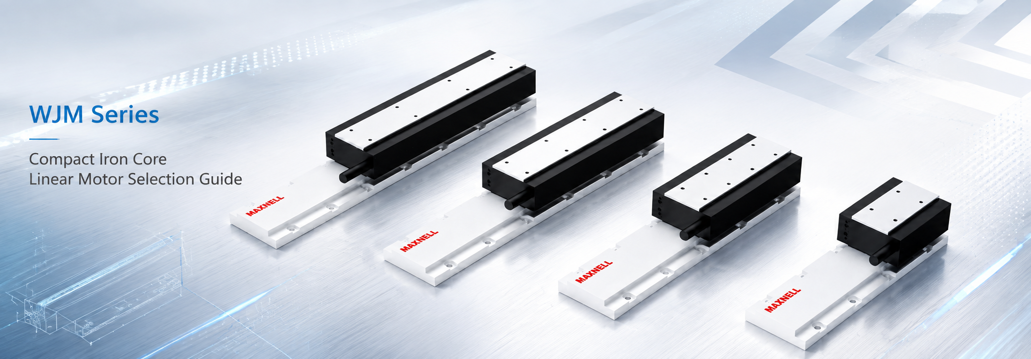
WJM linear motor selection should begin with the motion task, not with the largest force number in the product table. In laser inspection, electronics, measurement, and other compact automation equipment, installation space can matter as much as thrust. The compact iron core linear motor range is relevant when moderate force, rapid response, and custom direct-drive integration need to stay balanced. WJM does not replace WKM when substantially higher force is required, and it should not be treated as a complete guided stage such as NK.
WJM selection in one sentence: calculate peak and continuous demand from the real production cycle, then confirm mover width, motor length, stator arrangement, guide stiffness, encoder requirements, thermal conditions, cable routing, and service space before fixing one exact configuration.
Where WJM Fits in Compact Direct-Drive Motion
WJM is most useful when machine packaging and dynamic performance carry similar weight. A camera head, optical component, inspection sensor, electronic handling tool, or measurement probe may need fast positioning while the surrounding machine leaves little room for a large motor assembly.
In that situation, selecting a much larger motor only for additional force reserve can work against the original design goal. Extra motor size can increase integration demands, while stronger acceleration reaction can place greater demands on the base, guide support, carriage plate, and tooling structure. The useful question is whether one WJM configuration meets the actual motion profile with adequate thermal and mechanical margin.
Direct drive removes a screw or belt transmission from the main force path, which supports rapid response and reduces transmission wear. It does not remove the need for a rigid guide, suitable feedback, stable cable routing, a compatible servo drive, and a machine frame that can absorb acceleration forces. A correctly sized motor on a flexible camera bracket can still produce a slow move-and-settle cycle.
A practical WJM fit profile
Available motor width is restricted by the machine or surrounding process tooling.
The axis needs direct drive rather than a belt or screw transmission.
Required continuous thrust remains within an appropriate WJM configuration.
Short acceleration events need higher peak thrust without sustained heavy loading.
Move time and settling time both influence production output.
The machine already has, or genuinely needs, a custom guide and encoder arrangement.
Moving tooling consists of cameras, sensors, probes, optical heads, fixtures, or similar compact assemblies.
The real production duty cycle and local thermal environment can be defined.
WJM becomes less attractive when sustained force or acceleration demand moves beyond its practical range. That comparison should then move toward WKM. If the project mainly needs a ready-guided motion structure rather than motor components for a custom axis, NK changes the system boundary. If very smooth low-speed motion, low vibration, or cogging sensitivity dominates the process, an ironless architecture deserves comparison before WJM is fixed.
WJM Model Comparison for Early Selection
The current WJM range includes WJM30, WJM50, WJM80, and WJM100. The families differ in published continuous thrust, peak thrust, and mover width. Several motor and stator lengths add configuration choices within each family.
Use the table as an early engineering screen. It can remove families that do not fit the force or width requirement, but it cannot confirm a final motor by itself. The complete motion cycle, available force at operating speed, cooling condition, drive limits, stroke arrangement, guide structure, feedback system, and installation envelope still need to describe one consistent configuration.
| WJM family | Published thrust range | Published package reference |
|---|---|---|
| WJM30 | Continuous thrust: 117–430 N Peak thrust: 117–868 N | Mover width: 50 mm Motor lengths: 56 / 96 / 176 mm Stator lengths: 80 / 200 / 400 mm |
| WJM50 | Continuous thrust: 76–240 N Peak thrust: 201–750 N | Mover width: 75 mm Motor lengths: 56 / 96 / 176 mm Stator lengths: 80 / 200 / 400 mm |
| WJM80 | Continuous thrust: 113–360 N Peak thrust: 300–1120 N | Mover width: 100 mm Motor lengths: 56 / 96 / 176 mm Stator lengths: 80 / 200 / 400 mm |
| WJM100 | Continuous thrust: 145–460 N Peak thrust: 384–1420 N | Mover width: 125 mm Motor lengths: 56 / 96 / 176 mm Stator lengths: 80 / 200 / 400 mm |
How to read the table: each minimum-to-maximum range covers multiple mover configurations within that family. It is not an adjustable rating for one fixed motor. Confirm the force assigned to the exact motor length, permitted peak duration, cooling condition, drive requirement, and current datasheet before final selection.
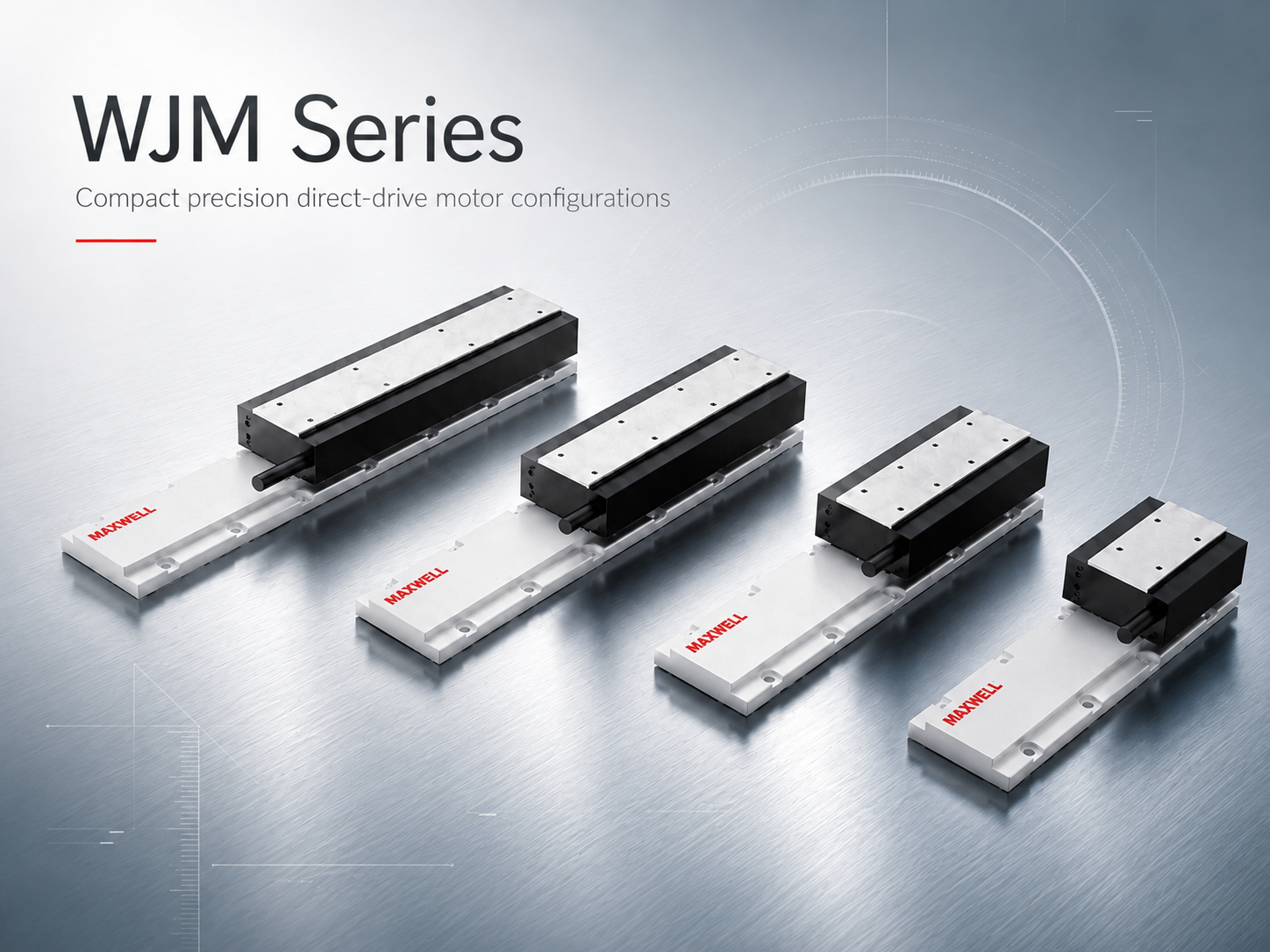
WJM Series mover and stator configurations for compact precision direct-drive axis design.
| View WJM Series |
Model numbers are not a simple force ladder
WJM30, WJM50, WJM80, and WJM100 should not be read as a simple progression in which every higher number automatically provides the next best sizing step. Published force ranges overlap, while mover width changes independently from the exact force operating point. A narrow machine may eliminate wider families immediately, but width should remain a physical constraint after required force has been calculated—not a replacement for that calculation.
The opposite mistake is also possible. A machine with additional space does not automatically benefit from the widest motor. Unused force capacity can increase integration demands without improving the production cycle. Establish the operating force first, then compare suitable configurations against mover width, motor length, drive capability, and the finished axis envelope.
Motor length and stator arrangement answer different questions
Motor length forms part of the force configuration inside a WJM family. Two machines with the same width restriction can need different motor lengths because their moving mass, acceleration, or continuous load differs. Tooling changes—additional lighting, guarding, sensors, mounting plates, or moving cable hardware—should trigger another sizing check even when the machine width stays unchanged.
Stator length mainly belongs to the travel arrangement. Required working stroke must remain separate from total motor installation length. The axis also needs mounting features, end clearance, homing and limit sensing, encoder hardware, cable exits, covers, and service access. A process that needs 200 mm of active movement may therefore need considerably more total mechanical space.
Screen WJM by Peak Force, Continuous Demand and Duty Cycle
WJM force sizing becomes clearer when three questions remain separate: what force appears during the hardest short event, what force the motor must sustain through production, and how much time the motor spends at each load level. Peak thrust, continuous capability, and duty cycle describe different parts of the operating requirement.
For a horizontal axis, the first inertial estimate is moving mass multiplied by acceleration. The useful mass figure is the complete moving assembly, not only the nominal payload. Include the carriage plate, brackets, camera or process head, sensors, lighting, covers, fixtures, cable carrier, and the moving section of cables or hoses. Add guide resistance, cable drag, external process force, and gravity only where they exist in the real machine.
Basic screening relationship: required force = complete moving mass × acceleration + friction + cable drag + process force + other predictable loads. A vertical or inclined axis also needs the gravity component, braking behavior, and a separate power-off holding or retention plan.
Peak thrust belongs to rapid acceleration, deceleration, reversal, or another brief process event. Continuous demand follows the repeating production cycle and the installed thermal condition. A motor can pass the peak check but run too close to its continuous thermal limit when high-force events repeat with little recovery time. The reverse can also happen: average heating may be acceptable while one acceleration pulse exceeds the available transient capability.
An RMS-style force check is useful when force changes through the cycle. It weights each force segment by duration and provides a preliminary comparison with continuous capability. Final confirmation still depends on the exact WJM configuration, force at operating speed, drive current and bus voltage, permitted peak duration, mounting, ambient temperature, and cooling conditions. For the complete calculation method, use SAHO's guides to continuous thrust vs peak thrust and linear motor sizing for payload, acceleration and cycle time.
Illustrative WJM shortlist: force first, width second
Consider a horizontal inspection carriage with 18 kg of complete moving mass and a target acceleration of 12 m/s². The inertial term is 216 N. If measured guide and cable resistance adds 24 N and a short process segment adds 30 N, the preliminary acceleration peak reaches 270 N. In an illustrative 2.5-second cycle with 0.15 seconds at 270 N, 0.7 seconds at 54 N, 0.15 seconds at 240 N during deceleration, and 1.5 seconds of genuinely unloaded dwell, the preliminary RMS force is approximately 93 N.
Now add a physical constraint: only 80 mm of motor width is available. WJM80 and WJM100 are removed by their published 100 mm and 125 mm mover widths. WJM30 and WJM50 remain possible family directions because their published widths are 50 mm and 75 mm. The table also shows family-level force capacity above the preliminary 270 N peak and 93 N RMS demand, but that does not confirm either motor. The exact mover length still has to pass its own peak, continuous, force-speed, drive, thermal, and installation checks.
This is the correct role of the family table: it creates a shortlist and explains why other families were removed. It does not allow the maximum force of one configuration to be combined with the dimensions or cooling condition of another. If production later shortens the dwell, adds tooling mass, or increases acceleration, the force-time calculation should be run again before mechanical release.
Include settling time in the production decision
Higher acceleration creates a stronger reaction in the base, gantry, guide support, carriage plate, and process bracket. A camera carriage may reach the commanded coordinate quickly while the camera still needs time to stabilize. The servo position error can already be small while the real optical or measurement point continues moving.
Usable cycle time therefore includes movement and settling. Extra WJM peak capability creates value only when the machine structure can convert it into shorter process-ready time. If a faster command produces an equal or longer settling delay, structural stiffness, tooling offset, jerk profile, or guide arrangement may be the more productive change.
Cooling, Encoder, Guide and Installation Checks
Once force and width have narrowed the list, the surrounding axis determines whether a proposed WJM configuration remains practical. These checks should happen before the mechanical structure is frozen.
| Check | What to confirm | Why it can change the selection |
|---|---|---|
| Thermal condition | Production duty, sustained force, enclosure temperature, nearby heat, airflow, mounting contact, and available cooling. | A motor that remains cool during occasional testing may accumulate heat during full-shift production. |
| Encoder | Required accuracy, repeatability, velocity stability, settling, scale accuracy, read-head location, and controller interface. | Higher resolution cannot correct a flexible process bracket or an unsuitable feedback location. |
| Guide and structure | Payload weight, side load, pitch/yaw/roll moments, center of gravity, rail spacing, preload, alignment, base stiffness, and tooling offset. | The motor supplies travel force; the guide and frame carry weight, moments, attraction, and acceleration reaction. |
| Installation envelope | Mover and stator mounts, guideways, encoder, working travel, end clearance, sensors, covers, cable exits, alignment access, and maintenance access. | A motor can fit in CAD while leaving no practical room to align the read head, bend cables, remove covers, or replace components. |
| Cable routing | Moving cable mass, carrier resistance, hose drag, minimum bend radius, fixed points, stroke-dependent load, and electrical shielding. | Changing drag can appear directly as a motion disturbance, especially during slow scanning and repeated short strokes. |
The process requirement should lead the encoder choice. An inspection carriage may mainly need repeatable return to a camera position, while a measurement platform may place greater emphasis on absolute behavior across the stroke. Those tasks do not necessarily need the same feedback strategy. The mechanical path between encoder and process point should also remain as rigid as the positioning target demands.
Tooling position can matter as much as tooling mass. A light optical assembly mounted far above the carriage can create substantial moment load and vibration. A heavier fixture placed closer to the guide plane can sometimes be easier to control. Supply total moving mass and center of gravity as separate inputs rather than assuming one payload number describes both motor force and guide behavior.
WJM vs WKM vs NK: Choose the Right System Boundary
WJM, WKM, and NK are not three products arranged on one performance ladder. WJM and WKM are motor-family decisions. NK changes the system boundary by providing a more integrated guided stage. An ironless motor creates a separate architectural branch when low disturbance and smooth motion carry more value than the iron-core direction.
| Direction | System role | When it becomes relevant |
|---|---|---|
| WJM | Compact iron-core mover and stator family. | Moderate thrust, restricted installation space, rapid response, and custom guide or encoder integration. |
| WKM | Higher-force iron-core mover and stator family. | Higher continuous or peak demand where heavier moving assemblies, stronger process forces, or more demanding industrial duty control the choice. |
| NK | Integrated linear motor stage / module. | A more complete guided motion structure when reducing separate motor, guide, encoder, and stage integration work is important. |
| JKA / JKB | Ironless direct-drive motor families. | Smooth low-speed motion, reduced cogging influence, low magnetic guide loading, or vibration-sensitive scanning and measurement. |
Keep WJM when compact packaging and custom geometry still matter
WJM is the natural direction when calculated force remains within one verified configuration and the machine needs control over guide spacing, encoder position, carriage geometry, and process tooling. That freedom has real value in compact OEM equipment. The tradeoff is greater responsibility for guide design, alignment, feedback integration, thermal planning, cable routing, and servo commissioning.
Move toward WKM when force becomes the limiting condition
A high force iron core linear motor becomes the more relevant comparison when moving mass, acceleration, external process load, or continuous demand moves beyond a suitable WJM configuration. Machine size alone does not establish that boundary: a compact process head can need high thrust when acceleration is aggressive, while a larger platform moving gently may remain thermally moderate.
Move toward NK when integration effort becomes the limiting condition
A linear motor stage starts from a more integrated motion structure rather than selecting only the motor and building guidance around it. NK can reduce development work when its module geometry already matches the machine. WJM remains more attractive when unusual guide spacing, a special encoder location, restricted process packaging, or a purpose-built moving structure makes custom integration worthwhile.
Compare ironless motion when smoothness is process-critical
If low force ripple, smooth velocity, vibration sensitivity, or cogging behavior becomes a primary constraint, compare the ironless branch rather than automatically moving to a larger iron-core motor. This question is particularly relevant to sensitive optical, scanning, and measurement motion. It does not mean that every precision axis needs an ironless motor; it means motion quality must become an explicit input when the process makes it critical. See the detailed ironless vs iron core linear motor comparison for the architecture-level decision.
WJM Applications: Match the Motion Profile, Not Only the Industry
WJM applications are easier to identify from their motion profile than from an industry name. A useful fit normally combines a compact moving assembly, moderate force demand, rapid positioning, and enough structural rigidity to make direct drive valuable.
| Application profile | Why WJM can fit | What can change the answer |
|---|---|---|
| Laser positioning and inspection | Compact packaging leaves room for optics, extraction, covers, sensors, and calibration hardware while supporting rapid point-to-point motion. | Settling at the optical point, process-head offset, cable or hose drag, local heat, and required scanning smoothness. |
| Electronics assembly and inspection | Cameras, probes, dispensers, test heads, and handling tools often make frequent short indexing moves in dense machine layouts. | High indexing frequency can make RMS demand more important than one peak; flexible tooling can make settling the true cycle limit. |
| Precision measurement | Stable repeatable positioning can matter more than maximum travel speed, and custom encoder placement may support the measurement architecture. | Guide friction, cable drag, encoder location, thermal growth, bracket stiffness, or a need for smoother ironless motion. |
| Semiconductor-related automation | WJM can serve a compact iron-core axis when force density and custom direct-drive integration match one specific task. | Each axis can have a different priority; scanning smoothness may point to ironless motion, while heavier tooling may point to WKM. |
Short-stroke indexing and longer scanning should not be treated as the same requirement. A short inspection move may spend most of its time accelerating, decelerating, and settling, making peak thrust and structural response the main concerns. A longer scan includes more constant-speed travel, so velocity stability, cable behavior, continuous demand, and thermal control gain importance. For broader application context, review SAHO's laser motion system page.
Information to Prepare for WJM Sizing
A useful WJM sizing request contains information that can change the model choice. A complete motion profile is more valuable than a long general description of the machine or a request based only on payload and stroke.
| Project item | Information to provide |
|---|---|
| Moving assembly | Complete moving mass, payload variation, tooling, fixture, carriage plate, cameras or process heads, covers, cable carrier, hoses, and center of gravity or tooling offset. |
| Stroke and envelope | Required working stroke, calibration or parking travel, available total axis length, permitted motor width and height, end clearance, and service access. |
| Motion profile | Normal operating speed, target acceleration and deceleration, move distance, move time, return profile, jerk limit where relevant, and the most demanding move identified separately. |
| External loads | Guide resistance, cable or hose drag, process force, gravity component, disturbance variation, and whether each load acts continuously or only during one segment. |
| Production duty | Acceleration, travel, deceleration, settling, process dwell, return, powered holding, true idle time, complete cycle time, moves per minute, and daily operating hours. |
| Motion quality | Required accuracy, repeatability, velocity stability, allowable settling time, measurement or image-capture timing, and any low-vibration or low-cogging requirement. |
| Installation | Horizontal, vertical, inclined, inverted, gantry, wall-mounted, or stacked-axis direction; guide layout; cable-chain direction; and power-off holding or retention requirements. |
| Thermal and environment | Expected local temperature, enclosure, airflow restrictions, nearby heat, contamination, dust or particles, available cooling, and continuous high-force operating periods. |
| Feedback and control | Encoder type and resolution, servo drive, controller, motion network, current limits, available bus voltage, and whether the control architecture is fixed or still open. |
If a value is still uncertain: provide the expected figure and a credible worst case. If a drawing, force-time profile, or control specification is available, mention it in the contact request so the engineering team can confirm the appropriate way to send the file.
WJM Selection FAQ
Is WJM a complete linear motor stage?
No. WJM provides the iron-core mover and stator components used inside a direct-drive axis. Mechanical guidance, carriage and support structure, position feedback, servo drive, controller, cabling, safety provisions, and any required cooling still need to be included. When a more integrated guided motion structure is preferred, compare the NK Series.
Does a higher WJM model number always mean more usable force?
No. The family ranges overlap, and each range contains several mover configurations. Model choice must compare one exact motor length and its verified force, thermal condition, drive requirement, and physical width. The largest family number is not automatically the best next sizing step.
When should WKM be selected instead of WJM?
Move toward WKM when no suitable WJM configuration can meet peak demand, continuous thermal duty, force at speed, or justified engineering margin within the required installation. The decision should come from the motion profile rather than machine size or a preference for the stronger series.
Is stator length the same as usable stroke?
No. Working travel must be checked together with mover length, stator arrangement, mounting, homing and limit positions, end clearance, encoder hardware, cables, covers, calibration travel, and service access. The listed stator length should not be treated as the complete usable machine stroke.
What should be entered in the sizing request?
In the contact form's “Your Request” field, enter complete moving mass, stroke, available width, target speed and acceleration, cycle timing, installation direction, required accuracy or repeatability, settling requirement, thermal environment, and known encoder or controller information. Mention any drawing or force-time profile that is available.
A WJM decision should finish with one consistent motor-and-machine configuration, not with the maximum number in a family table. Moving load, stroke, speed, acceleration, force-time profile, installation direction, positioning requirement, and thermal environment establish the operating need. Guide stiffness, encoder location, cable behavior, drive capability, and service space then determine whether that performance can be delivered inside the finished machine.
For projects still deciding between screw, belt, direct-drive motor components, and integrated modules, see linear axis design for industrial automation. Once WJM has been identified as the likely direction, use the data table above to prepare a model-level sizing request.
Before final WJM confirmation: prepare the complete motion profile, check the full mechanical envelope, and record the feedback, drive, controller, thermal, and environmental conditions. If any input may change, include both the expected and worst-case value.
| Request Linear Motor Sizing |





















