

Date:2026-08-05 Click:281
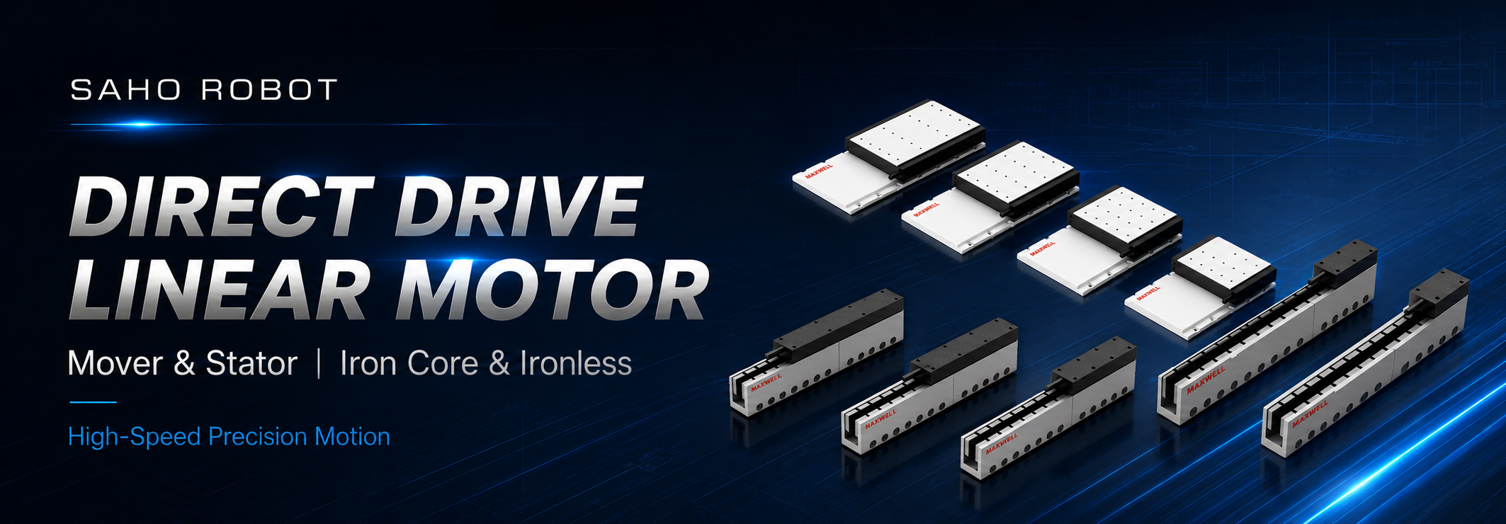
High Performance Linear Motor Solution for High-Speed and Precision Motion Applications
SAHO direct drive linear motors are designed for applications that require high speed, fast dynamic response and precision positioning. Instead of converting rotary motion through a ball screw, belt, coupling or gearbox, the motor generates linear force directly between the mover and stator.
Removing the mechanical transmission stage helps reduce backlash and common transmission wear points while supporting smooth repetitive motion. Final performance still depends on the complete motion system, including the guideway, encoder, structural rigidity, servo control, moving mass and thermal condition.
Selection should follow a clear path: understand the mover and stator first, compare iron core and ironless technology, then check thrust, speed, duty cycle, travel, cooling and feedback requirements. If the machine builder needs a complete guided axis instead of motor components, the next product level is a linear motor stage or linear motor module.
What Is a Direct Drive Linear Motor?
A direct drive linear motor is an electromagnetic actuator that converts electrical energy directly into straight-line motion. Electromagnetic force is produced along the travel direction, so the motor does not require a rotary-to-linear transmission mechanism.
Without a screw, timing belt, coupling or gear reducer in the main force path, the motor can respond quickly to control commands and support rapid acceleration, deceleration and precise repetitive movement. This makes direct drive useful in semiconductor equipment, laser processing, inspection, measurement, precision assembly and other automation systems.
Direct drive alone does not guarantee final positioning accuracy. Encoder quality, guide accuracy, mounting flatness, structural rigidity, payload stiffness, cable drag, thermal behavior and servo tuning remain part of the complete performance result.
Linear Motor Mover & Stator
The two core components are the mover and the stator. In technical documentation, they may also be described as Primary (Mover) and Secondary (Stator). Some industry catalogs use Forcer and Magnetic Track for the same functional relationship.
The mover and stator work together to generate direct linear force. The mover is integrated with the moving structure, while the stator forms the magnetic path along the required travel. Together, they form the core motor components before guideway, encoder and carriage integration.
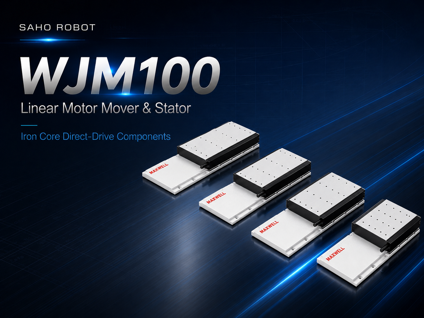
Direct Drive Linear Motor Components: SAHO WJM100 iron-core configurations illustrate how mover and stator components form the motor before guideway, encoder and carriage integration.
View WJM Iron Core Linear Motor
Linear Motor Mover
The mover is the force-producing component connected to the moving structure. Its size and configuration should be reviewed against required thrust, moving mass, acceleration, current demand, cable routing and cooling.
Supports fast acceleration and deceleration.
Provides direct dynamic response without a mechanical transmission stage.
Can be integrated into custom precision platforms and linear motion systems.
Linear Motor Stator
The stator provides the magnetic field required for direct linear force generation. Stator sections can be arranged according to the required travel, but usable stroke must also include mover length, end clearance, installation alignment and the total machine envelope.
Supports flexible stroke configuration.
Allows multiple stator sections to be arranged for longer travel.
Can be adapted to customized motion-system layouts.
| Technical component | Main function | Key integration checks |
| Primary (Mover) | Produces controlled electromagnetic force and is connected to the moving structure. | Moving mass, acceleration, current, cooling, cable routing and mounting interface. |
| Secondary (Stator) | Provides the magnetic field along the required motion path. | Stator length, travel, installation alignment, mounting surface and machine envelope. |
Iron Core & Ironless Linear Motor Technology
SAHO provides iron core and ironless direct-drive linear motor directions for different motion requirements. Neither structure should be treated as a universal upgrade over the other. The choice depends on required thrust, acceleration, motion smoothness, vibration sensitivity, duty cycle, cooling and available installation space.
| Comparison point | Iron Core Linear Motor | Ironless Linear Motor |
| Main strength | High thrust density and strong force output. | Smooth motion with very low cogging behavior. |
| Typical review direction | Higher thrust, stronger acceleration, heavier moving structure and compact force requirements. | Low vibration, smooth scanning, precision measurement and sensitive inspection. |
| Engineering checks | Magnetic attraction, guide loading, cogging behavior, stiffness and thermal design. | Required thrust, motor envelope, moving mass, cooling and feedback quality. |
| Typical applications | Semiconductor equipment, industrial automation, laser processing and precision handling. | Optical inspection, measurement systems, precision assembly and laboratory automation. |
When an Iron Core Linear Motor Is the Better Direction
Review an iron core design when the machine needs stronger thrust from a compact motor size, rapid acceleration with a larger moving structure or higher dynamic force during repeated indexing. Magnetic attraction, guide loading, cogging behavior and structural stiffness should be included in the mechanical review.
Peak thrust alone is not enough for selection. Continuous thrust, RMS force, duty cycle and thermal margin must also support the real production cycle.
When an Ironless Linear Motor Is the Better Direction
Review an ironless design when smooth velocity, low vibration and low cogging are especially important. This direction can be valuable for optical inspection, precision measurement, scanning, laboratory systems and other processes where small motion disturbances can affect quality.
Ironless selection still requires a full force and thermal review. Moving mass, acceleration, duty cycle, cooling, encoder performance and installation size must support the required motion profile.
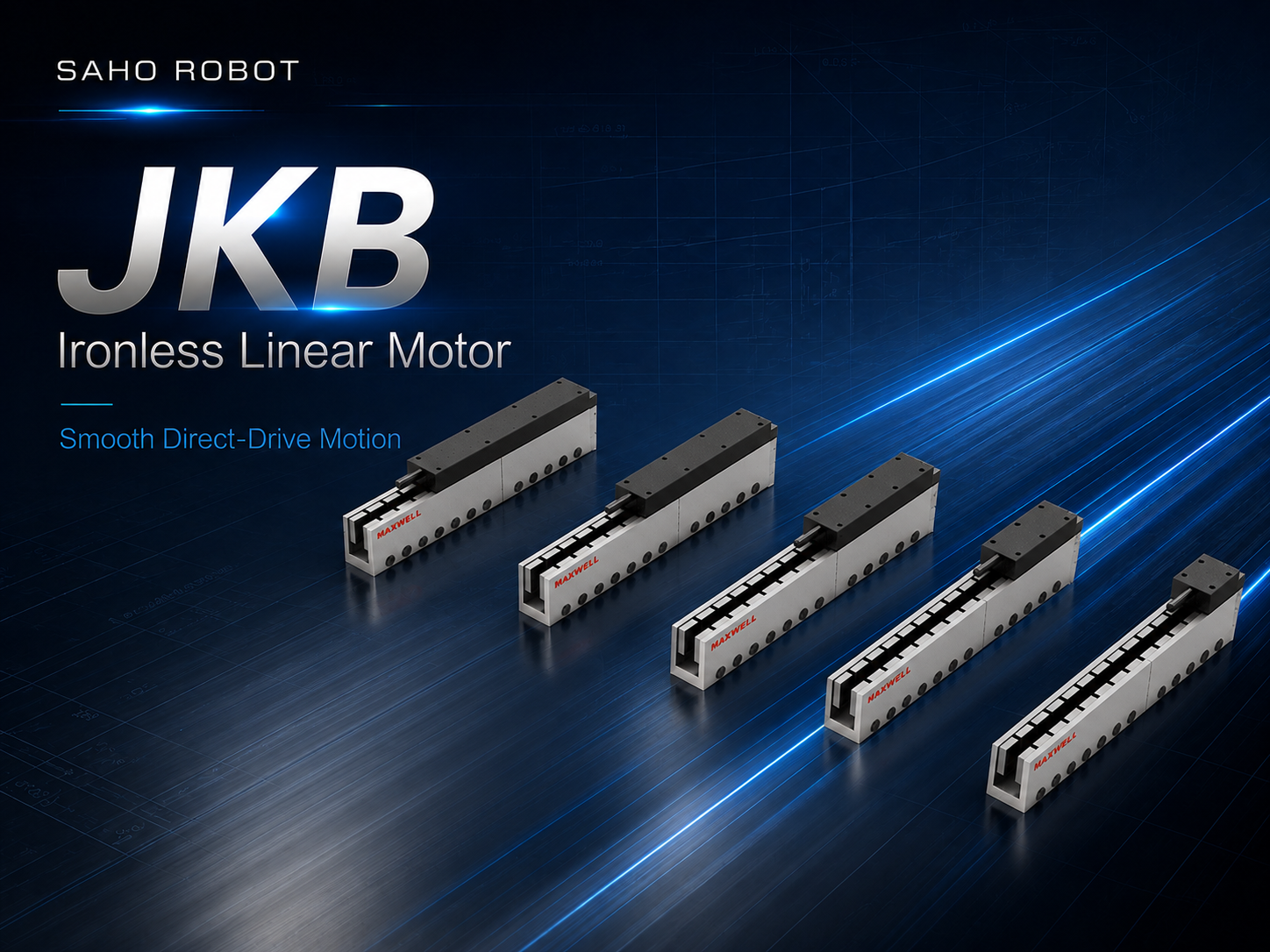
Ironless Linear Motor Example: SAHO JKB configurations illustrate an ironless direct-drive structure for smooth motion, low cogging and low-vibration positioning.
View JKB Ironless Linear Motor
Advantages of a Direct Drive Linear Motor
| Advantage | Practical meaning | Machine value |
| High speed and fast response | Force acts directly along the travel direction. | Supports rapid indexing, short moves and repeated acceleration and deceleration. |
| Smooth motion | The main drive path does not rely on belt stretch or screw friction patterns. | Useful for scanning, inspection, laser and process-on-the-move applications. |
| Precision positioning potential | Encoder feedback controls position without transmission backlash in the motor drive path. | Supports stable positioning when the mechanical and control system are properly designed. |
| Low-maintenance drive structure | No ball screw, timing belt, coupling or gear reducer is required for force conversion. | Reduces common transmission wear points and supports long operating schedules. |
| Flexible stroke design | Stator sections can be arranged according to the required travel and machine layout. | Supports customized motion systems and different installation lengths. |
Applications of Direct Drive Linear Motors
Semiconductor Equipment
Direct drive motion can support wafer handling, inspection systems and precision positioning platforms where responsive movement, repeatable positioning and controlled thermal behavior are important.
Laser Processing Equipment
Laser cutting, marking and precision laser positioning may require smooth travel, rapid indexing or fast contour movement. Motor response, encoder feedback, controller tuning and frame rigidity all affect the final path quality.
Machine Vision and Optical Inspection
Camera positioning, line-scan inspection and optical measurement often depend on steady velocity and low vibration. Ironless motors are commonly reviewed for sensitive smooth-motion requirements, while iron core motors can be evaluated where stronger thrust is needed.
Industrial Automation
Direct drive motors can be integrated into high-speed transfer, precision assembly, XY positioning and customized multi-axis automation. In gantry or stacked-axis systems, the complete moving structure must be included in the force and guide-loading calculation.
How to Select the Right Direct Drive Linear Motor
Motor selection should begin with the real movement profile rather than maximum speed or one peak-force value. The profile should show travel, acceleration, deceleration, time at speed, dwell time, cycle frequency and the thermal condition of the machine.
1. Calculate the Total Moving Mass
Include the mover, carriage, fixture, product, camera, sensor, cable chain, air tubes, adapter plates and protective parts. Center of gravity and moment loading also matter when the motor is integrated into a complete mechanical axis.
2. Separate Continuous Thrust From Peak Thrust
Continuous thrust determines whether the motor can support the repeated production cycle within its thermal limit. Peak thrust supports short acceleration, deceleration and disturbance loads. RMS force, duty cycle, ambient temperature and cooling method should be reviewed together.
3. Check Force at the Required Speed
The selected motor must provide the required force at the intended operating velocity. Review the force-speed curve, drive voltage, current demand and back-EMF condition instead of assuming that low-speed peak force remains available across the full speed range.
4. Define Stroke and Stator Length
Effective travel should include process stroke, homing distance, safety clearance and end limits. Stator length must be planned together with mover length and the physical machine envelope.
5. Match Encoder and Control Requirements
Encoder resolution, feedback type, controller bandwidth, drive current and servo tuning should match the required accuracy, velocity stability and settling time. High-resolution feedback cannot compensate for a flexible frame or poor guide alignment.
6. Confirm Cooling, Installation and Environment
Available cooling space, mounting interface, cable direction, ambient temperature and contamination level influence the final configuration. Vertical or inclined axes also require a separate load-holding or braking strategy because the motor does not mechanically lock the axis when power is removed.
Customized Direct Drive Linear Motor Solutions
SAHO can review direct drive linear motor configurations according to the machine layout and motion requirement. The engineering discussion should be based on verified application data rather than a general request for the largest or fastest motor.
Motor size and installation envelope
Continuous and peak thrust requirement
Stroke length and stator arrangement
Encoder and feedback configuration
Natural, air or water cooling direction where applicable
Single-axis or multi-axis integration requirements
Data Required for Motor Selection
A motion diagram or machine layout is usually more useful than a single payload or speed value. The following information helps narrow the motor, cooling and integration direction.
| Data to provide | Details to prepare | Why it matters |
| Moving mass | Carriage, tooling, product, cables, fixtures and mover mass. | Used to calculate acceleration force and motor size. |
| Motion profile | Move distance, speed, acceleration, deceleration, dwell time and cycles per minute. | Defines peak force, RMS force and dynamic demand. |
| Travel and space | Effective stroke, total available length, end clearance and mounting space. | Helps determine stator arrangement and mechanical layout. |
| Precision target | Repeatability, absolute accuracy, velocity stability and settling time. | Guides encoder, guideway and control-system selection. |
| Electrical and thermal conditions | Supply voltage, drive current, duty cycle, ambient temperature and cooling method. | Confirms force at speed and sustainable continuous operation. |
| Environment | Dust, particles, cleanliness, vibration and protection requirements. | Helps decide whether exposed motor components or a protected complete module is more appropriate. |
Related Product: Linear Motor Stage / Linear Motor Module
A direct drive linear motor refers to the motor-level mover-and-stator system. If the project needs the guideway, carriage and mechanical axis structure integrated as a more complete positioning product, choose a linear motor stage or linear motor module.
SAHO NK Series represents this complete-axis product level. It should be evaluated after the motor-level force, motion and installation requirements are clear, rather than treated as another name for the mover-and-stator motor itself.
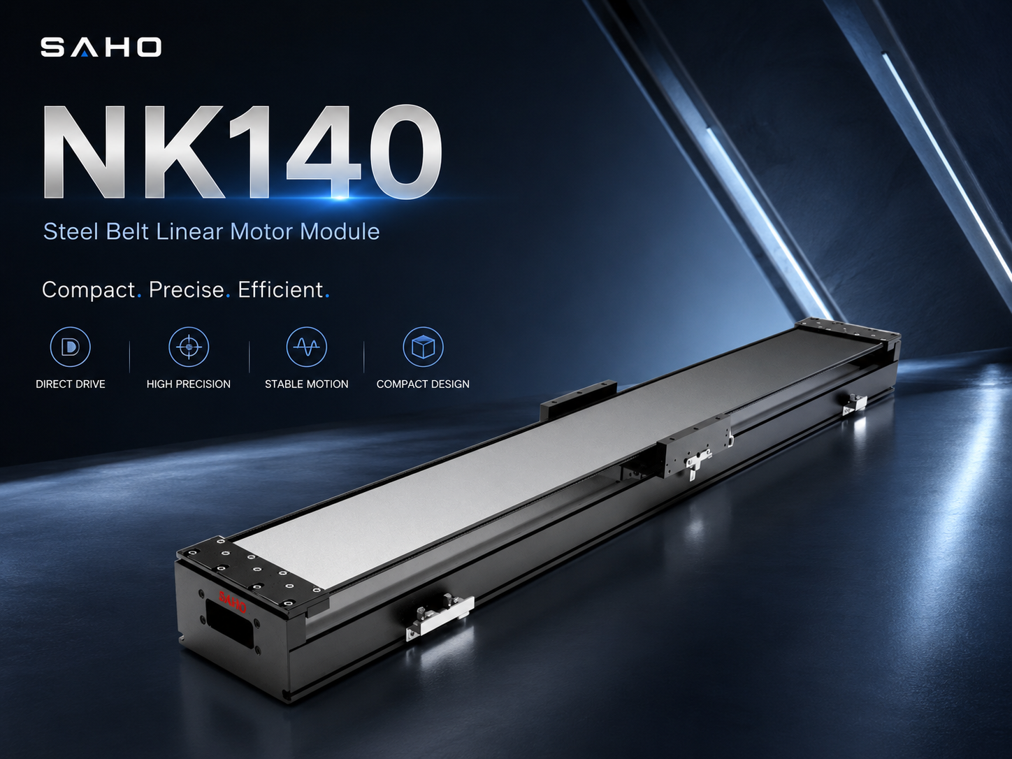
NK Series: a complete linear motor stage / linear motor module for machine builders that need guided motion and a ready-to-integrate axis.
View NK Series Linear Motor Module
Frequently Asked Questions
What are the main components of a direct drive linear motor?
The main components are the mover and stator. Technical documentation may describe them as Primary (Mover) and Secondary (Stator). The mover produces driving force, while the stator provides the magnetic field along the motion path.
Is a direct drive linear motor the same as a linear motor stage?
No. The direct drive linear motor is the motor-level mover-and-stator system. A linear motor stage or linear motor module adds guided motion and a mechanical axis structure. SAHO NK Series belongs to this complete stage/module level.
How do I choose between iron core and ironless?
Iron core motors are normally reviewed when thrust density and stronger acceleration are important. Ironless motors are reviewed when smooth motion, low cogging and low vibration are especially important. Final selection should include force, speed, duty cycle, cooling, feedback and installation limits.
Can stator sections be combined for longer travel?
Multiple stator sections can be arranged according to the required stroke. The final layout must include mover length, usable travel, end clearance, mounting alignment and the total machine envelope.
What data should be sent before requesting a recommendation?
Send moving mass, stroke, top speed, acceleration, movement cycle, continuous operating time, precision target, installation direction, available space, cooling method, drive voltage, feedback requirement and working environment. A machine drawing or motion profile will make the review more accurate.
Choose the Motor From Real Application Data
A direct drive linear motor should be selected from the complete motion requirement. Continuous thrust, peak thrust, force at speed, moving mass, travel, feedback, cooling and installation conditions must work together rather than being checked as isolated specifications.
Choose mover and stator components when the machine builder will design the guide, encoder and platform around the motor. Choose a linear motor stage or linear motor module when the project needs a more complete guided axis. This keeps the motor product and complete module product clearly separated from inquiry through final selection.







-
-
 English
 -
 Français
 -
 Deutschland
 -
 Italia
 -
 Polska
 -
 España
 -
 Русский язык
 -
 日語
日語 -
 한국
한국 -
 Türkiye
 -
 português
 -
 بالعربيةês
 -
 Tiếng Việt
 -
 คนไทย
คนไทย -
 简体中文
简体中文 -
繁體中文
-