

Date:2026-07-07 Click:354
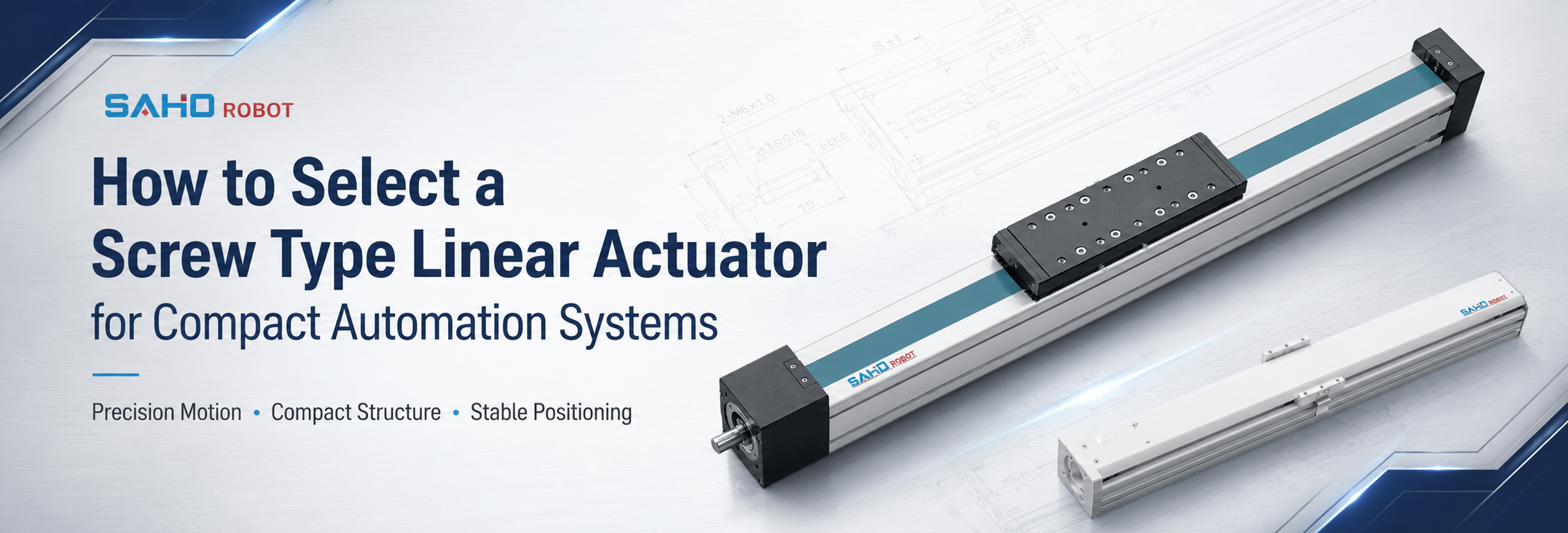
In compact automation systems, a screw type linear actuator supports accurate short-stroke movement, stable thrust, controlled positioning and clean mechanical integration. A reliable selection process should not start with product size alone. It should begin with stroke, payload, screw lead, motor position, sensor space, installation direction and the available machine envelope. This approach avoids selecting a module that appears compact in a catalogue but creates clearance or performance problems after installation.
At the same time, compact equipment often needs more than a small linear module. It may require a vertical lifting axis, a precision assembly stage, a fixture feed axis, a camera adjustment axis or a short-stroke inspection platform. The actuator must match both the motion requirement and the surrounding structure.
Compact Automation Needs Motion and Space Logic
Compact automation usually leaves limited space around the motion axis. A module may look suitable in length, yet the motor may interfere with a guard, frame plate, cable chain or sensor bracket. Therefore, product selection should consider the whole machine layout. Service access for motor removal, sensor adjustment, lubrication, and cable replacement should also be visible in the drawing.
In many small automation cells, the actuator also carries tooling that creates offset load. A fixture plate, nozzle, camera, gripper, pressure head or sensor bracket may sit away from the carriage center. As a result, moment load can become more important than the basic payload number.
Compact machines also run repeated short cycles. The axis may move only 80 mm, 150 mm or 300 mm, but it may repeat the movement thousands of times per shift. Speed, acceleration, screw lead and duty cycle must be checked together.
For broader automation background, the A3 Association for Advancing Automation provides industry-level insight into automation technologies and applications. However, final actuator selection still depends on application data, machine layout and motion requirements.
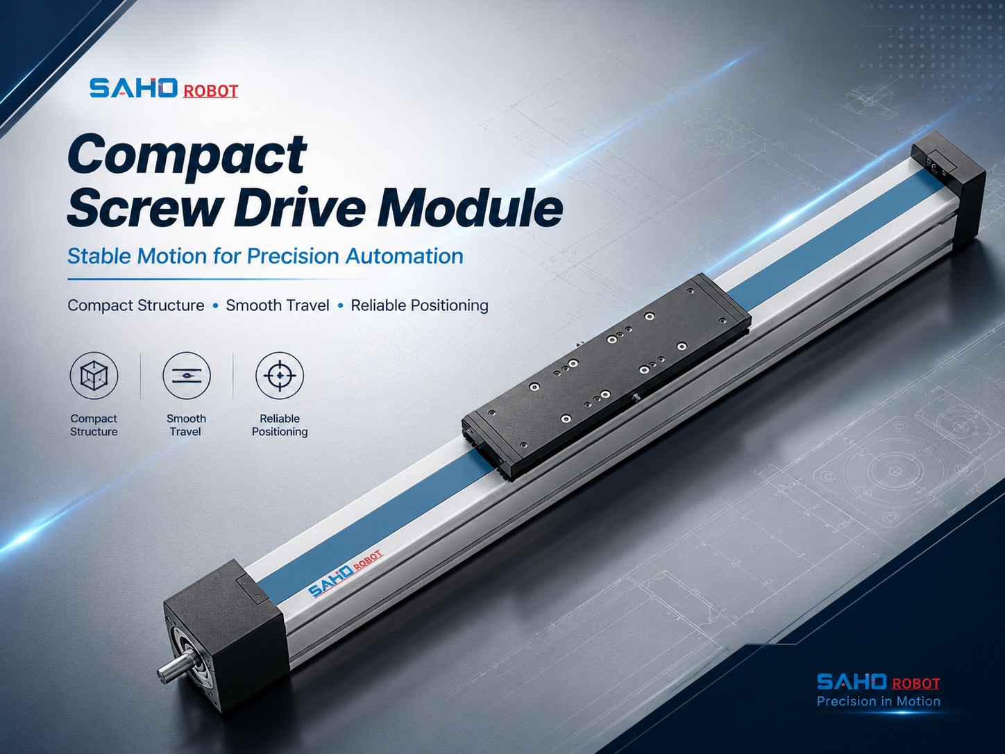
JTS80 screw drive module for compact clean-room positioning and short-stroke automation layouts.
Key Benefits for Compact Automation Systems
Stable positioning in a limited footprint
Screw drive motion is useful when a compact machine needs accurate stop positions. The screw converts motor rotation into controlled linear movement. This allows the carriage to move to a set position with stable travel behavior.
In assembly and inspection equipment, this stability helps reduce repeated manual adjustment. A fixture can return to the same process point, and a sensor can stay aligned with the target area. Process consistency becomes easier to maintain.
Useful thrust for lifting, feeding and guided tool approach
Screw drive actuators are often selected when the axis needs more thrust than a simple transfer mechanism. The screw lead, motor torque and guide structure work together to support controlled force. This makes the drive type practical for lifting, feeding, guided positioning and tool-approach tasks.
However, thrust should not be judged only by payload weight. Acceleration, vertical direction, tooling offset and safety factor also affect sizing. Engineering evaluation should include both static load and dynamic motion data.
JTS, SDM, or SDH can position a fixture and control the tool-approach path. When the main process requires direct pushing, pulling, or controlled electric-actuator movement, the SEH Series electric linear actuator should also be evaluated. This keeps positioning modules and direct process actuators clearly separated.
Better repeatability for process control
Third, compact automation often depends on repeatable positioning rather than long travel speed. For example, a small dispensing station may require the nozzle to return to the same height and path. Similarly, a vision station may require a camera to stop at a stable inspection distance.
In these cases, repeatability directly affects process quality. The actuator, motor, screw, guide, mounting base and controller settings all influence the final result. Therefore, the motion axis should be selected as a complete system rather than as an isolated part.
Clean integration with motor and sensor planning
Compact layouts also require careful motor and sensor planning. An inline motor may increase total length, while a folded motor may need extra side space. Motor position should be checked before the machine drawing is released.
Sensor space is also important. Origin sensors, limit sensors, sensor flags and cable clamps need enough room around the actuator body. Sensor planning belongs in the early selection checklist, not only in the final wiring stage.
Suitable for modular single-axis and multi-axis systems
Screw drive modules can work as single axes or as part of XY, XZ and XYZ structures. A compact machine may use one short X-axis for fixture feeding and one vertical Z-axis for tooling movement. Actuator width, carriage height and mounting interface should support system-level integration.
When one actuator carries another axis, the lower module must support the combined moving mass. Meanwhile, the upper module must stay rigid under tool offset. Stacked-axis selection should check payload, moment load, base stiffness and cable route together.
Applications: Where Screw Drive Motion Fits Best
Precision assembly equipment
Precision assembly equipment often needs short and repeatable linear movement. The actuator may move a fixture under a press head, align a small component, or feed a part carrier into the assembly area. Stroke control and carriage rigidity are important.
Compact assembly stations may have many parts close to the motion axis. Guards, air tubes, sensors, clamps and frame plates can limit available space. Motor position and sensor side should be confirmed during the initial layout review.
Electronic component handling
Electronic component equipment needs smooth and stable motion. Small parts can shift during fast starts or sudden stops. A screw drive actuator can help create controlled short-stroke movement for fixtures, inspection plates and positioning stages.
For example, connector assembly, sensor module handling, PCB fixture movement and camera inspection stages may all use compact linear axes. In these applications, repeatability, low vibration and clean cable routing are more important than long travel distance.
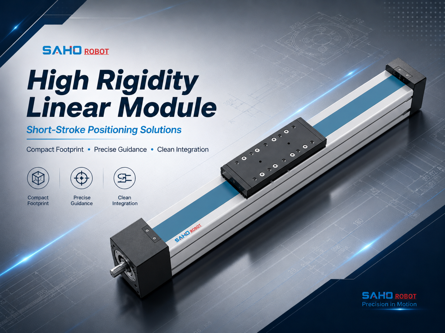
JTS100 screw drive module for clean-room automation, lithium battery equipment and electronic component assembly.
Inspection and test stations
Inspection equipment often needs a stable approach position. The actuator may move a camera, probe, laser sensor or measuring head toward a product. Repeatable stopping and guide stability help reduce inspection variation.
However, inspection axes may also require smooth low-speed travel. A very large screw lead may support speed, but it may not support fine movement as well as a smaller lead. Screw lead should match both speed and measurement needs.
Dispensing, coating and small processing systems
In dispensing and coating equipment, the actuator may move a nozzle, valve, tube holder or fixture plate. Smooth motion and stable height control can support better process consistency. At the same time, payload offset must be checked because tooling often sits away from the carriage center.
Air tubes and fluid lines can also pull on the moving head. If cable or tube routing is too tight, the carriage may experience extra drag. The machine design should reserve a safe cable path through the full stroke.
Vertical positioning and compact lifting axes
Vertical axes need special attention because gravity acts along the motion direction. A compact lift may move a camera, fixture, clamp, nozzle or small tooling plate. Payload, screw lead, brake requirement and safety margin should be checked carefully.
In vertical motion, the actuator must not only move the load. It must also hold the load during stop conditions. Motor brake selection, screw lead and control logic should be reviewed before final model confirmation.
Selection Tips: A Practical Checklist for Engineering Review
A good selection process moves from application data to product direction, then from product direction to model size. This approach avoids a common problem. A module may fit the machine drawing, yet fail the real payload, speed or service access requirement.
The following checklist focuses on the details that decide compact automation performance. The most reliable review uses the actual machine drawing rather than judging the actuator from catalogue dimensions alone. Each item affects another item. For example, stroke affects total length, screw lead affects speed and thrust, and motor position affects available installation space.
| Selection item | Why it matters | Practical check |
| Stroke | Defines working travel and total actuator length. | Add approach distance, home position and end clearance. |
| Payload | Affects screw thrust, guide load and motor torque. | Include tool, fixture, part, cable drag and bracket weight. |
| Screw lead | Balances speed, thrust and positioning resolution. | Use smaller lead for thrust and fine control; larger lead for speed. |
| Motor position | Controls machine footprint and service clearance. | Confirm inline, folded, left-side or right-side arrangement early. |
| Sensor space | Prevents interference after installation. | Reserve room for origin, limit, sensor flag and cable clamp. |
1. Define working stroke before actuator stroke
Working stroke means the travel used by the process. Actuator stroke must also include home position, overtravel allowance, sensor trigger area and safe clearance. The selected stroke should be slightly larger than the visible process travel.
For example, a fixture may need 280 mm of usable travel. However, the axis may still need additional distance for home return and mechanical clearance. As a result, a 300 mm or 350 mm stroke may be more practical than a value that only matches the process path.
2. Check load weight and load center
Payload should include every moving item on the carriage. Tooling, fixtures, brackets, sensors, grippers, cables and carried parts should be counted together. Acceleration can increase the real load on the screw and guide.
However, weight alone is not enough. The distance between the carriage surface and the load center creates moment load. A small but tall bracket can require a stronger actuator than expected.
3. Match screw lead with speed and thrust
Third, screw lead means the linear distance traveled during one screw rotation. A larger lead can increase travel speed at the same motor speed. However, it usually reduces mechanical advantage for thrust.
By contrast, a smaller lead can support stronger thrust and finer control. It is often useful for vertical lifting, guided tool approach, inspection and precise dispensing. Therefore, screw lead should be selected after speed, load and positioning requirements are known.
4. Confirm speed, acceleration and cycle time
Compact machines often perform short repeated moves. A short move may still create high dynamic load if acceleration is aggressive. Move distance, move time, acceleration and dwell time should be provided together.
At the same time, maximum speed is not always the best target. Smoother motion can reduce vibration, protect fixtures and improve sensor reading. The selected speed should support both cycle time and process stability.
5. Separate accuracy and repeatability
Also, accuracy and repeatability are different. Accuracy describes how close the carriage reaches a commanded position. Repeatability describes how consistently it returns to the same point under the same conditions.
In many compact automation systems, repeatability is the main concern. The station is usually taught once, then repeats the same motion cycle. However, measurement equipment may also require stronger absolute accuracy, so the required tolerance should be stated clearly.
6. Confirm motor direction before drawing release
Motor position can decide whether the actuator fits the final machine. Inline mounting is simple, but it increases total length. Folded mounting can reduce length, but it needs side clearance.
In compact equipment, the motor may face a conveyor, feeder, door, frame plate or upper axis. Motor direction should be reviewed on the complete machine layout. This check should happen before purchasing parts or releasing drawings.
7. Reserve space for sensors and cables
Sensor space is easy to miss during early selection. Origin sensors, limit sensors and sensor flags need physical mounting room. Cable clamps and connectors need enough bending space.
The actuator should be checked at both stroke ends. A sensor bracket must not collide with the carriage, tooling or protective cover. Early sensor planning can prevent commissioning delays.
8. Review installation direction and mounting surface
Installation direction changes the load condition. Horizontal mounting, side mounting and vertical mounting place different forces on the guide and screw. The same payload may require different model decisions in different orientations.
The mounting surface should also be flat and rigid. A precise actuator cannot perform well on a weak or twisted base. The machine frame should support the actuator with enough stiffness and alignment quality.
Decision Logic: Which SAHO Series Fits the Application?
The application environment helps narrow the product direction. Cleaner compact equipment, lithium battery equipment and electronic component assembly may point toward JTS. General automation, higher-load positioning and vertical axis applications may point toward SDM.
Then, the model size should be selected by load, stroke, speed, repeatability, screw lead and installation direction. A compact body is useful only when it can also support moment load and service access. Product direction and layout review should work together. No single series is the best choice for every compact machine, so product category and model size should be confirmed separately.
| Application condition | SAHO direction | Selection reason |
| Clean-room or cleaner automation layout | JTS Series | Suitable product direction for compact clean-room screw drive positioning. |
| Compact built-in motion with limited installation space | SDH Series | Built-in actuator direction for space-sensitive equipment layouts. |
| Electronic component assembly | JTS or SDM | Depends on load, stroke, installation space and environment. |
| General automation positioning | SDM Series | Integrated ball screw and guide structure supports stable positioning and repeatability. |
| Vertical or higher-load axis | SDM with brake review | Load holding, thrust and safety margin need detailed checking. |
| Long-stroke high-speed transfer | Review belt drive direction | Long travel transfer may not need screw thrust or fine control. |
Related Products for Compact Screw Drive Selection
JTS Series: compact screw drive direction for cleaner automation
The JTS Series is a useful product direction when compact screw drive movement is needed in cleaner automation layouts. It is suitable for lithium battery equipment, electronic component assembly and short-stroke positioning tasks that need stable linear guidance.
JTS models can support compact axes where the actuator must fit into a limited machine envelope. However, the final model should be selected after checking payload, stroke, motor position and sensor clearance. JTS is best reviewed with a simple machine layout drawing.
SDH Series: compact built-in actuator direction
The SDH Series provides a built-in actuator direction for compact guided motion where installation space is a primary design constraint.
It can be considered when the axis must fit close to tooling, covers, sensors, or adjacent mechanisms. Moving load, tool offset, stroke, motor direction, and mounting rigidity still require engineering review.
SDM Series: integrated ball screw direction for general automation
The SDM Series is designed for stable positioning, high repeatability and high-load linear motion in general automation environments. It is suitable for precision assembly, inspection equipment, laser processing, electronic component production, battery equipment, vertical axis applications and multi-axis systems.
The SDM range includes multiple model sizes. This makes it practical for projects that may need anything from a compact positioning axis to a stronger vertical or higher-load axis. This range makes SDM a practical product direction when rigidity, repeatability and load capacity are important.
However, compact integration still needs layout review. Motor direction, cable outlet, sensor side and service space should be confirmed before the actuator is fixed in the machine design. SDM selection should include both motion data and installation details.
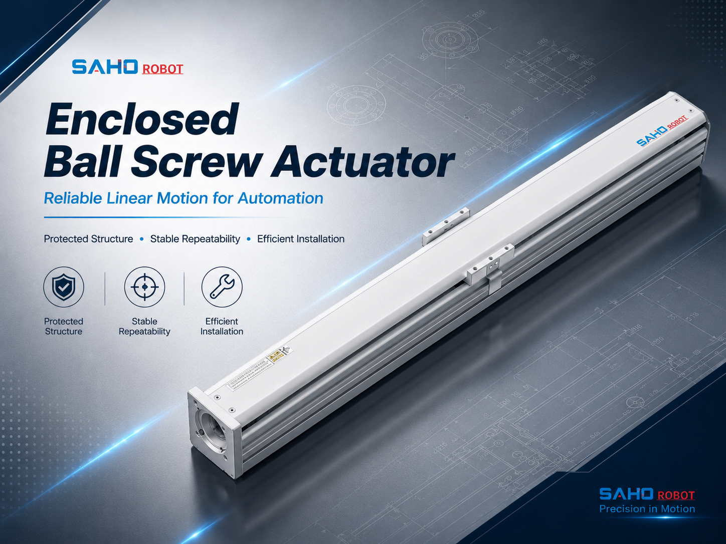
SDM75 ball screw module for general automation, compact positioning and stable linear motion.
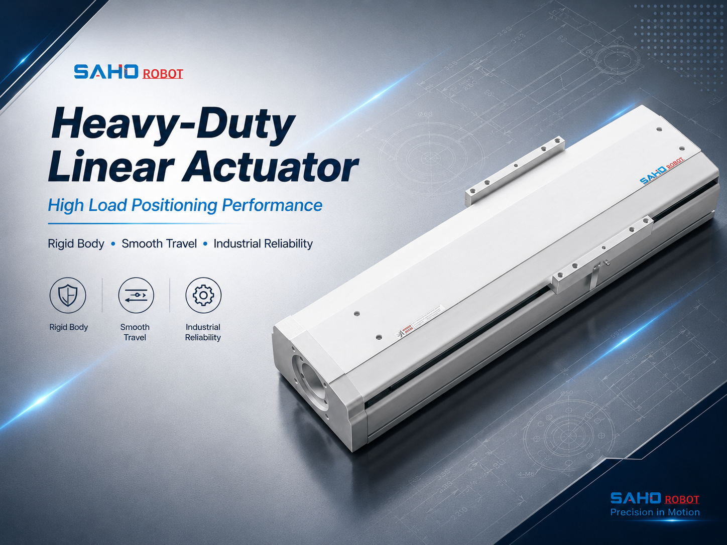
SDM210 ball screw module direction for higher-load positioning, vertical axes and compact multi-axis automation.
Sizing Information to Send for SAHO Review
Sizing becomes more accurate when the motion task is described with clear numbers. Terms such as “fast,” “heavy” or “compact” are not enough for model selection. Stroke, load, speed, accuracy and installation direction should be listed in a simple table.
A simple sketch can reduce misunderstanding. The drawing should show stroke direction, motor side, tool position, sensor space, cable route and surrounding frame parts. As a result, SAHO can review both actuator performance and mechanical clearance.
| Data item | Details to prepare |
| Stroke | Working travel, total stroke, home position and safety clearance. |
| Load | Payload mass, fixture mass, tool mass and load center offset. |
| Speed | Move distance, move time, acceleration and cycle frequency. |
| Accuracy | Repeatability target, positioning tolerance and process sensitivity. |
| Installation | Horizontal, vertical or side mounting, plus motor and sensor direction. |
| Environment | Clean-room requirement, dust, oil mist, temperature and operating hours. |
FAQ
When should a screw type actuator be used instead of a belt actuator?
Generally, screw drive motion fits compact axes that need higher thrust, better rigidity, shorter stroke control and repeatable positioning. Belt drive motion is often better for long-stroke transfer and high-speed movement. The decision depends on whether the axis needs precise force and positioning or long travel efficiency.
For example, vertical lift axes, tool approach axes, inspection stages and compact assembly axes often favor screw drive motion. However, long transfer axes may favor belt drive motion. The application function should decide the drive type before the model is selected.
How do stroke and load affect selection?
Stroke affects total actuator length, screw behavior and machine footprint. A longer stroke may need more installation space and speed review. Working travel should be separated from home position and safety clearance.
Meanwhile, load affects screw thrust, guide capacity, motor torque and brake planning. The load center position also matters because offset tooling creates moment load. Both payload weight and payload position should be checked during sizing.
What details should be sent to SAHO for sizing?
For efficient sizing, SAHO should receive stroke, payload, load center offset, move distance, move time, acceleration, repeatability target, installation direction, motor brand, motor position, sensor location and working environment. A simple layout drawing also helps confirm clearance.
If the axis is vertical, the request should also mention brake requirements and safe stop expectations. If the station has dust, oil, clean-room needs or continuous operation, those details should also be included. This information helps match the actuator to the real operating condition.
Can screw drive modules support compact multi-axis systems?
Yes. Screw drive modules can support XY, XZ and XYZ structures when payload, overhang and mounting stiffness are checked correctly. However, the lower axis must carry the moving mass of the upper axis. Therefore, combined load review is important.
Cable routing becomes more important in stacked axes. Motor cables, sensor cables and tooling lines should move smoothly through the full stroke. Actuator orientation and cable chain direction should be planned at the same time.
Conclusion: Build the Selection Around Stroke, Load and Space
In summary, compact automation needs an actuator that fits the machine space and supports the motion task. Stroke, payload, screw lead, motor position, sensor space, accuracy target and installation direction all affect the final decision. Selection should combine motion data with layout review. A balanced choice reduces redesign risk during commissioning and keeps the axis practical to maintain after the machine enters production.
Three practical actions before final selection:
First, prepare a simple layout showing stroke direction, motor side, payload position, sensor area and nearby frame parts.
Second, list stroke, load, speed, acceleration, repeatability target, duty cycle and installation direction in one sizing table.
Finally, compare JTS and SDM product directions with SAHO before fixing the machine drawing and motor layout.
For compact automation systems that need controlled travel, stable thrust and clean integration, the Screw Type Linear Actuator remains a strong selection path when sizing data is complete. Send SAHO the required stroke, load, speed, accuracy, installation direction, motor position and sensor space so the final actuator direction can match the real machine structure.
Need a compact screw drive axis for an automation project?
SAHO can review stroke, load, speed, accuracy, motor position, sensor space and installation direction to recommend a suitable JTS or SDM product direction.







-
-
 English
 -
 Français
 -
 Deutschland
 -
 Italia
 -
 Polska
 -
 España
 -
 Русский язык
 -
 日語
日語 -
 한국
한국 -
 Türkiye
 -
 português
 -
 بالعربيةês
 -
 Tiếng Việt
 -
 คนไทย
คนไทย -
 简体中文
简体中文 -
繁體中文
-