

Date:2026-07-03 Click:293
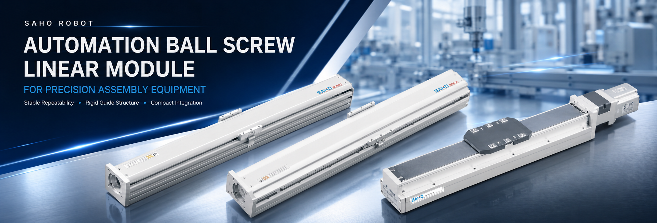
Precision assembly equipment depends on stable motion, controlled positioning, and repeatable process results. An automation ball screw linear module should therefore be selected as part of the complete machine structure rather than treated as a simple moving component. The module must work with the tooling, fixture, servo motor, controller, mounting plate, sensors, and production cycle.
In precision assembly applications, screw-driven motion can support component positioning, dispensing, inspection, fastening, fixture movement, tool approach, and compact multi-axis systems. The correct selection depends on stroke, moving load, tool offset, speed, repeatability, installation direction, environmental conditions, and long-term maintenance access.
Precision Assembly Starts with Stable Linear Motion
Small motion errors can become visible production problems. A connector may not seat correctly, a dispensing path may shift, an inspection camera may lose its intended working distance, or a fastening tool may approach the part at the wrong position. The motion axis must repeat the required travel path with controlled speed, stable guidance, and predictable stopping behavior.
Modern assembly machines also place several functions inside one compact frame. A single station may include feeders, fixtures, electric screwdrivers, cameras, sensors, pneumatic components, safety covers, and cable carriers. The linear module must fit into this structure without creating unnecessary interference or reducing service access.
The working cycle is rarely one constant-speed movement. It may include fast transfer, controlled deceleration, slow approach, process dwell, and fast return. Screw lead, guide rigidity, moving mass, servo motor selection, controller tuning, and installation direction all influence how smoothly this sequence is completed.
Precision assembly also depends on reliable measurement and clearly defined tolerances. The NIST metrology resources explain the importance of measurement science and measurement quality in engineering. Inside an assembly machine, stable mechanical motion helps create repeatable conditions for process control and inspection.
Key Benefits for Precision Assembly Equipment
Stable Repeatability for Controlled Process Results
A ball screw drive converts servo motor rotation into controlled linear travel. Combined with a suitable linear guide structure, it helps the carriage return consistently to the required working point during positioning, dispensing, inspection, loading, or fastening.
In many assembly stations, repeatability is more important than maximum speed. A dispensing nozzle must maintain a stable gap from the product surface. An inspection camera must return to a defined viewing position. A fastening tool must approach the same screw location during every cycle.
Repeatable motion also makes process troubleshooting easier. When the axis position remains stable, variation caused by fixtures, materials, sensors, tools, or controller settings becomes easier to identify.
Rigid Linear Guidance for Tool Alignment
The ball screw produces the drive force, while the linear guide supports the carriage and controls its travel path. Guide rigidity becomes especially important when the tooling creates side load, offset load, or reaction force.
A tool may be relatively light but mounted on a long bracket. The distance between the carriage surface and the tool center creates moment load on the guide structure. For this reason, module selection should consider both total moving mass and tool offset.
Probing, clipping, fastening, insertion, and fixture locking can also create reaction force. A rigid guide structure helps keep the tool aligned with the fixture and reduces unwanted tilt during approach or contact.
Compact Integration Inside Dense Machine Frames
Assembly equipment often has limited space around the working area. The linear axis may share the frame with feeders, cameras, cable carriers, grippers, safety doors, fixtures, and control components. An integrated screw-driven module can simplify the mechanical layout compared with assembling separate screw, rail, bearing, and support components.
A compact and organized axis layout can also improve service access. Engineers should still leave enough space for sensor adjustment, cable routing, motor removal, lubrication, tool replacement, and fixture maintenance.
Servo Motor Matching for Smooth Motion Control
Servo motor matching affects available torque, acceleration, travel speed, and settling time. The motor should be reviewed together with moving mass, screw lead, stroke, duty cycle, and the required motion profile.
A larger motor does not automatically create better motion. Poor matching between motor inertia, load inertia, screw lead, coupling, and controller tuning can cause overshoot, vibration, or unnecessary equipment size.
A smaller screw lead can support higher thrust and finer travel per motor revolution, while a larger lead can support higher linear speed. The appropriate combination depends on load, stroke, process speed, approach behavior, and takt time.
| Assembly Requirement | Motion Need | Selection Value |
| Component positioning | Repeatable stop point and rigid guidance | More consistent fixture and tool alignment |
| Dispensing height | Stable low-speed motion and repeatable gap | More uniform bead, dot, or coating result |
| Camera inspection | Low vibration and predictable settling | More stable viewing and measurement conditions |
| Tool approach | Controlled acceleration and guided travel | Lower risk of tool tilt or contact error |
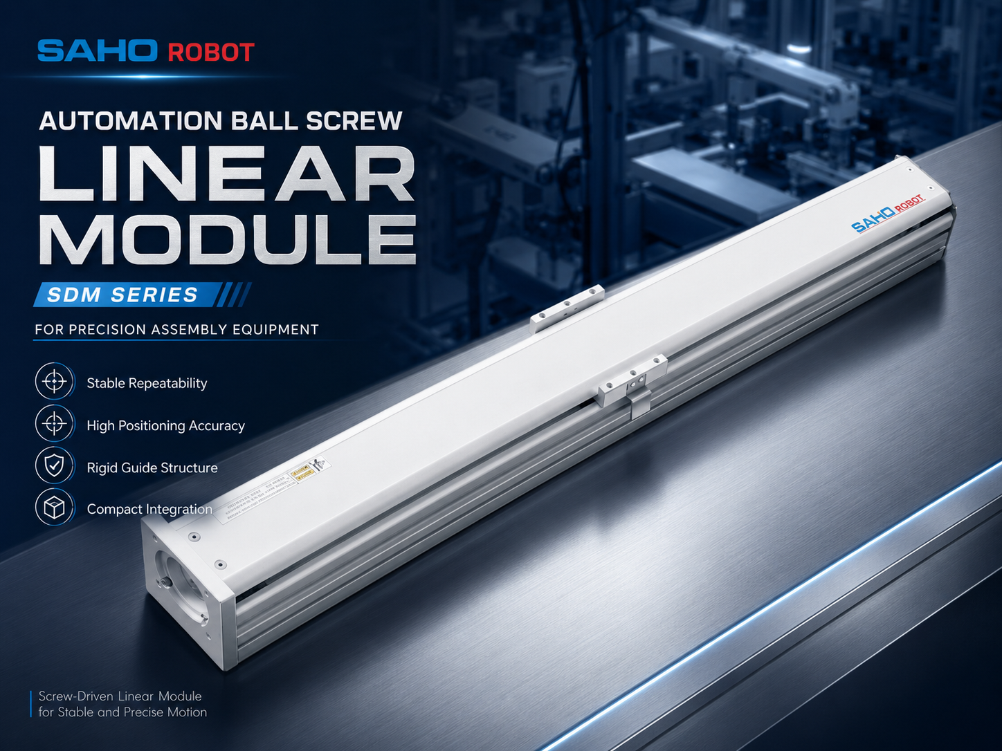
SDM Series supports stable screw-driven positioning, high repeatability, and rigid guided motion for precision assembly equipment.
Applications in Precision Assembly Equipment
Electronic Component Assembly
Electronic component assembly commonly requires compact tooling, short or medium travel, and repeatable position control. The axis may move a connector fixture, guide a test probe, position a camera, or carry a small fastening or dispensing head.
Small parts can be sensitive to side force and positioning error. A shifted connector, bent pin, or unstable inspection distance can affect the completed assembly. Guide stiffness, smooth acceleration, controlled stopping, and fixture alignment should be considered during the station design.
Tool Approach, Insertion, and Pressing Stations
Screw-driven modules can position the tooling, move a fixture, and control the approach path before the assembly operation begins. Rigid guidance helps keep the tool aligned as it approaches a connector, clip, bearing, pin, or fixture location.
The positioning axis and the process actuator should not automatically be treated as the same product. SDM or SDH may be selected for accurate travel and tool positioning. When the main requirement is servo-controlled pushing, pulling, pressing, or direct actuator movement, the SEH Series electric linear actuator should also be evaluated.
Vertical installation also requires additional review. Gravity acts on the moving assembly during motion and stopping. Brake motor selection, moving mass, safe stop logic, mounting rigidity, and suitable mechanical protection should be confirmed before the final design.
Inspection and Measurement Fixtures
Inspection equipment depends on repeatable positioning. A camera, laser sensor, or measuring probe may need the same distance and angle relative to the part during every cycle. Stable axis motion helps maintain consistent inspection conditions.
Settling time is also important. If the axis reaches the commanded position but continues to vibrate, the vision or measurement system may need an additional delay before data capture. Guide rigidity, moving mass, acceleration, deceleration, and servo tuning all influence this behavior.
Dispensing, Gluing, and Coating Stations
Dispensing equipment needs a consistent nozzle position. The gap between the nozzle and product surface can affect bead width, dot size, coating shape, and material distribution. The axis should support smooth low-speed travel and repeatable stop positions.
A dispensing cycle may combine slow working motion with faster non-working travel. Screw lead, servo motor selection, acceleration, and controller tuning should be considered together so the system remains stable during material application without creating unnecessary cycle time.
Battery and Small Module Assembly
Battery and small module assembly may combine fixture positioning, alignment, inspection, dispensing, fastening, and controlled tool movement. One axis may carry the fixture while another axis moves a camera, nozzle, or working tool.
These machines often use several axes inside a compact enclosure. Each axis should be selected according to its actual moving load, stroke, installation direction, speed profile, duty cycle, and position within the complete multi-axis structure.
| Application | Typical Axis Role | Main Selection Focus |
| Electronic assembly | Fixture, probe, camera, or tool positioning | Repeatability, compact layout, smooth stopping |
| Insertion and tool approach | Tool alignment and controlled travel | Guide rigidity, moment load, installation direction |
| Inspection equipment | Camera, laser sensor, or probe positioning | Low vibration, repeatable distance, settling time |
| Dispensing and gluing | Nozzle height and path control | Stable low speed, repeatable gap, smooth travel |
| Battery and module assembly | Fixture, alignment, inspection, or tool movement | Compact integration, duty cycle, multi-axis load |
Selection Tips Before Confirming a Model
Define Effective Stroke and Safe Travel
Stroke should include more than the visible working distance. The axis may need additional travel for origin return, sensor placement, tool clearance, part loading, safe approach, and maintenance access.
Excessive stroke should also be avoided. A longer axis can increase machine size, screw length, cost, and travel time. The most suitable stroke normally provides enough process clearance without adding unnecessary length.
Calculate Moving Load and Tool Offset
The moving load should include every component carried by the carriage: tooling, fixture plate, bracket, camera, screwdriver, suction cup, cable carrier, tube, sensor, and the heaviest product handled by the axis.
Weight alone is not enough. The distance from the carriage surface to the tool center creates moment load. A lightweight tool on a long bracket may require more guide capacity than a heavier load mounted close to the carriage.
Define Speed, Acceleration, and Settling Time
Speed should be defined as part of the complete production cycle. The axis may move quickly through free space, decelerate before the process area, approach the part slowly, hold position, and then return at a different speed.
Maximum speed alone does not determine productivity. An axis that stops quickly but vibrates for a long time may increase total cycle time. Acceleration, deceleration, load rigidity, servo tuning, and settling time should be reviewed together.
Separate Accuracy from Repeatability
Accuracy describes how closely the carriage reaches the commanded position. Repeatability describes how consistently it returns to the same position under similar conditions. These requirements should be defined separately.
Repeatability often has a direct effect on assembly consistency. Absolute accuracy becomes more important when the axis must match a camera coordinate system, robot position, measurement reference, or precision fixture.
Confirm Installation Direction and Brake Requirement
Horizontal, vertical, side-mounted, and inverted installations create different load conditions for the ball screw, guide, motor, lubrication system, and mounting structure. Installation direction should be included in the first model-selection request.
For vertical axes, gravity continues to act on the load during stopping and power-off conditions. A brake motor, mechanical lock, counterbalance, or another suitable safety measure may be required according to the application risk and equipment design.
Match the Servo Motor and Mechanical Module
Motor torque, speed, inertia, encoder feedback, brake option, controller settings, and screw lead all influence the final motion result. Motor selection should be reviewed with the actual load, stroke, acceleration, and duty cycle.
Motor mounting direction also affects the machine frame. A straight motor installation may conflict with a feeder, safety door, cable carrier, frame post, or maintenance area. This detail should be confirmed before the final 3D layout is approved.
Review the Working Environment
Dust, oil mist, adhesive mist, metal particles, temperature, and cleaning methods can affect long-term operation. The working environment helps determine suitable cover options, lubrication intervals, cleaning procedures, sensor protection, and maintenance access.
| Selection Data | Information to Prepare | Why It Matters |
| Stroke | Working travel, home position, sensor space, and service clearance | Helps avoid an undersized or unnecessarily long axis |
| Moving load | Tool, bracket, fixture, cable, sensor, and product mass | Supports guide, screw, and motor sizing |
| Tool offset | Distance from carriage surface to load center | Helps evaluate moment load and guide stability |
| Motion profile | Working speed, return speed, acceleration, deceleration, and dwell | Supports cycle-time and settling analysis |
| Position requirement | Accuracy, repeatability, and process tolerance | Connects module selection with assembly quality |
| Installation | Horizontal, vertical, side-mounted, inverted, or stacked | Confirms load direction, brake needs, and mounting method |
| Environment | Dust, oil, adhesive mist, temperature, and cleaning conditions | Helps define protection and maintenance requirements |
SDM or SDH for Precision Assembly Equipment
SDM Series for General Screw-Driven Positioning
The SDM Series is suitable for stable positioning, high repeatability, and higher-load screw-driven motion in general automation equipment. It can support precision assembly, inspection, electronic production, battery equipment, vertical-axis applications, and multi-axis systems.
SDM can work as a single axis or form part of an XY, XZ, YZ, or XYZ structure. The model should be selected according to load, stroke, screw lead, speed, installation direction, repeatability requirement, and the rigidity of the complete machine frame.
SDH Series for Compact Built-In Motion
The SDH Series provides a built-in actuator format for compact guided motion. It is relevant when the axis must fit inside a dense equipment structure or when motor placement, tool access, and machine footprint are important design factors.
Compact construction does not replace engineering calculation. Moving load, tool offset, stroke, speed, installation direction, brake requirements, and mounting rigidity should still be reviewed before a model is confirmed.
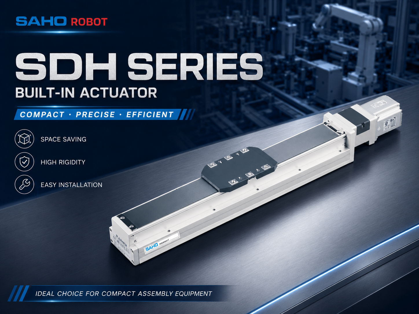
SDH Series supports compact guided motion where machine footprint, installation space, and tool access are important.
| Selection Point | SDM Series | SDH Series |
| Primary direction | General screw-driven positioning with rigid guided motion | Compact built-in actuator for guided motion |
| Typical equipment | Assembly, inspection, battery equipment, and multi-axis systems | Compact stations, integrated tool areas, and space-sensitive machines |
| Main selection focus | Load, rigidity, stroke, speed, and system integration | Footprint, motor direction, guide support, and access space |
| Recommended when | Stable positioning and broader model selection are required | Compact installation is a major design requirement |
How the Module Fits into Multi-Axis Assembly Systems
Many assembly machines use more than one linear axis. An XY table may position a fixture under a fixed tool, while an XYZ system may move a working head between several process points. The selected modules must connect reliably with mounting plates, brackets, sensors, cable carriers, and adjacent axes.
In a stacked system, the lower axis carries the upper axis, motor, tooling, cables, and workpiece. The base axis may therefore require greater rigidity and load capacity. A machine may use a larger SDM axis at the base and a compact SDH axis for the upper working movement.
Multi-axis systems also need coordinated homing, limit protection, cable routing, and service access. These points should be included in the mechanical and control design before the equipment is assembled.
Common Model-Selection Mistakes
Selecting Only by Load Weight
Load weight does not describe the complete application. Tool offset, acceleration, process force, mounting direction, and bracket rigidity can create additional guide load. Weight and moment load should always be considered together.
Ignoring the Approach Motion
A tool may travel quickly through free space but require a slower approach near the product. Selecting the axis only from maximum travel speed can overlook the low-speed stability, deceleration, dwell, and return movements that affect the real process.
Confirming Motor Direction Too Late
Motor direction can create hidden interference with feeders, safety doors, frame posts, cables, and maintenance areas. Motor orientation and brake requirements should be confirmed during the early equipment-layout stage.
Forgetting Maintenance Access
Ball screws and guideways require appropriate lubrication, inspection, and clean operating conditions. The machine frame should leave enough room for routine service, sensor replacement, cable inspection, and cleaning around the axis.
Using a Positioning Module for Every Process Task
A screw-driven positioning module is not automatically the best solution for every pushing or pressing task. The motion objective should be defined first. SDM and SDH are suitable directions for guided positioning, while SEH should also be reviewed when the process is primarily based on controlled electric-actuator movement.
Information to Prepare for Model Recommendation
Complete application data makes model selection faster and more reliable. Before requesting a recommendation, prepare the following information:
Required working stroke, home position, safety clearance, and service space.
Total moving mass, including tooling, fixture, cables, sensors, and product.
Distance between the carriage surface and the center of the moving load.
Working speed, return speed, acceleration, deceleration, and cycle time.
Required accuracy, repeatability, and process tolerance.
Horizontal, vertical, side-mounted, inverted, or stacked installation.
Servo motor preference, brake requirement, and motor mounting direction.
Working environment, duty cycle, dust, oil, adhesive mist, and temperature.
Available drawings, sketches, mounting dimensions, and surrounding equipment layout.
With this information, SAHO can review the appropriate product series, model size, screw lead, stroke, motor configuration, mounting direction, sensor position, and multi-axis integration requirements.
FAQ
How does a ball screw linear module support precision assembly?
The ball screw converts motor rotation into controlled linear movement, while the guide structure supports the carriage and controls its travel path. When the module, motor, load, and mounting frame are selected correctly, the axis can support repeatable positioning for inspection, dispensing, alignment, fastening, and fixture movement.
What information is needed before choosing a model?
The main information includes stroke, total moving load, tool offset, speed, acceleration, repeatability, accuracy, installation direction, duty cycle, motor preference, brake needs, and working environment. A simple equipment drawing can also help confirm mounting space and motor direction.
Should precision assembly use SDM or SDH?
SDM is a suitable direction for broader screw-driven positioning, higher-load applications, and multi-axis systems. SDH is a suitable direction when compact built-in construction and limited installation space are important. The final decision should be based on actual load, stroke, speed, accuracy, tool offset, and equipment layout.
Can a screw-driven module be installed vertically?
Yes. Vertical installation is common for inspection, tool approach, dispensing, and positioning applications. The design must account for gravity load, moving mass, brake motor requirements, mounting rigidity, safe stop behavior, and suitable mechanical protection.
Is a ball screw module suitable for force-controlled pressing?
A ball screw module can position the tool or fixture and control the approach path. When the main task is servo-controlled pushing, pulling, or pressing, the process requirements should be compared with a dedicated electric actuator such as the SEH Series before the final product direction is selected.
Conclusion: Build the Motion Axis Around the Assembly Process
Precision assembly equipment needs more than an actuator with enough travel. The complete motion axis must provide stable guidance, repeatable positioning, suitable speed, compact integration, reliable motor matching, and practical maintenance access.
An automation ball screw linear module should be selected from the real process data. SDM is suitable for broader screw-driven positioning and multi-axis automation, while SDH is useful for compact built-in guided motion. SEH should also be evaluated when the main process requires direct electric-actuator pushing, pulling, or pressing movement.
The best model is not simply the largest or fastest option. It is the module that matches the required stroke, load, tool offset, speed, accuracy, repeatability, installation direction, duty cycle, and machine layout with a suitable safety and performance margin.
Request Precision Assembly Module Selection SupportSend the required stroke, moving load, tool offset, speed, repeatability, installation direction, motor preference, duty cycle, and working environment. SAHO can help compare SDM, SDH, SEH, and related motion solutions for the assembly process. |







-
-
 English
 -
 Français
 -
 Deutschland
 -
 Italia
 -
 Polska
 -
 España
 -
 Русский язык
 -
 日語
日語 -
 한국
한국 -
 Türkiye
 -
 português
 -
 بالعربيةês
 -
 Tiếng Việt
 -
 คนไทย
คนไทย -
 简体中文
简体中文 -
繁體中文
-