

Date:2026-07-10 Click:1131
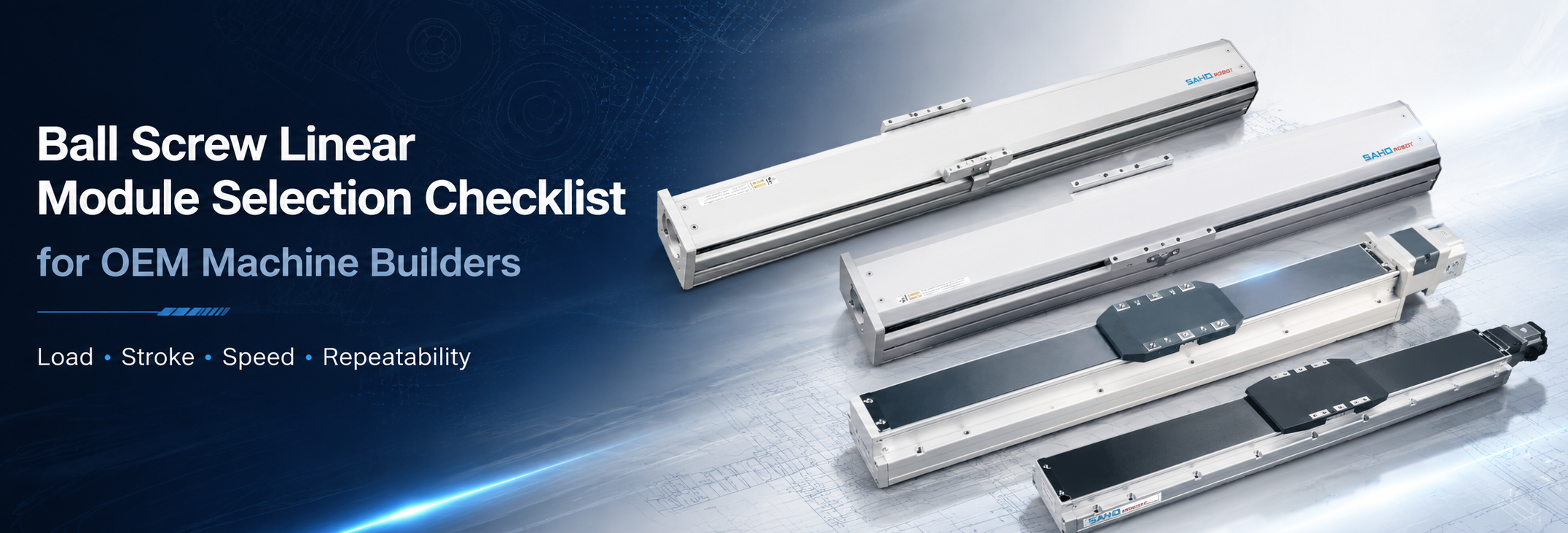
A ball screw linear module should be selected from real machine conditions, not from a model name alone. Load, stroke, speed, repeatability, duty cycle, mounting direction, environment, motor brand, and drawing files should be confirmed before a final recommendation. This checklist helps OEM engineering teams prepare clear motion data, compare suitable SAHO screw drive products, and move faster from concept design to quotation.
In many automation projects, the actuator looks like a simple component. In reality, it affects the whole machine structure, motor sizing, frame design, wiring path, service access, and long-term maintenance plan. A structured selection process reduces repeated communication and makes the final specification easier to approve.
Key Benefits of a Screw Drive Linear Axis
A screw drive actuator converts motor rotation into controlled straight-line movement through a precision screw and guide structure. This makes it suitable for applications that need stable positioning, controlled thrust, and repeatable motion, including assembly, inspection, testing, dispensing, fixture transfer, tool approach, and small-part handling equipment.
Screw drive motion also supports compact machine layouts. The actuator combines a screw, guide, carriage, and profile into one motion unit, so the mechanical design can be cleaner than building every guide rail, screw support, coupling, and cover from separate parts.
In many short- and medium-stroke tasks, the structure can provide higher rigidity than a long-stroke transfer axis. The final result still depends on frame stiffness, bracket design, and load position, but a suitable screw drive product gives the machine a strong foundation for controlled positioning.
| Benefit | Practical Value | Typical Use |
| Stable positioning | Supports repeatable stops during indexing and inspection. | Fixture transfer, camera positioning, testing stations. |
| Higher rigidity | Helps handle process force and compact load movement. | Probing, clamping, tool approach, vertical Z-axis motion. |
| Cleaner integration | Reduces separate mechanical parts in the axis design. | Assembly cells, multi-axis platforms, compact machines. |
| Flexible motor matching | Can be discussed with common servo motor brands and mounting needs. | OEM equipment using Mitsubishi, Panasonic, Yaskawa, Delta, or Inovance motors. |
Industrial automation continues to place higher demands on motion reliability, integration time, and repeatable production quality. For wider automation industry background, the Association for Advancing Automation provides industry-level resources. This article focuses on practical selection data for SAHO screw drive linear motion products.
Applications That Benefit From This Selection Checklist
Precision Assembly Equipment
Precision assembly equipment often needs repeatable short-stroke movement. A product nest may move between loading, positioning, checking, and unloading points. The actuator must support stable stops under the actual fixture weight, tool load, and process condition.
Many assembly machines also use compact layouts. The motion axis may sit close to pneumatic cylinders, sensors, cable tracks, safety covers, and frame plates. Stroke, motor side, sensor side, and mounting height should be checked together before selecting the product size.
For pressing-related stations, SDM or SDH can position the fixture, support guided tool approach, or move the working axis into position. When the main process requires direct pushing, pulling, lifting, or controlled electric-actuator movement, the SEH Series electric linear actuator should also be reviewed.
Inspection and Vision Positioning
Inspection equipment often values stability more than peak speed. A camera, probe, laser gauge, or sensor head must return to the same inspection point many times. Repeatability, vibration control, and settling time should be reviewed together.
A vision axis may move a product under several camera positions. The travel distance may be moderate, but the process requires a clean stop before image capture. The motion profile should include acceleration, deceleration, dwell time, and acceptable vibration.
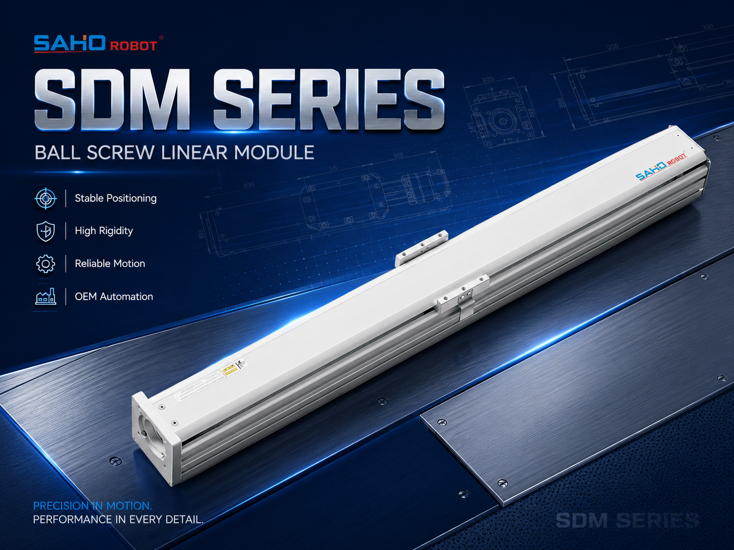
SDM Series is suitable for stable positioning, inspection equipment, and general automation axes.
Electronic Component Assembly
Electronic component production usually uses small parts, narrow fixtures, and controlled movement. The payload may look light, yet the process tolerance can be tight. Model selection should not depend only on load capacity.
The engineering team should also confirm straightness needs, repeat positioning tolerance, mounting flatness, and cable routing. The selected axis should leave enough room for wiring, sensors, and future maintenance to reduce hidden integration problems during assembly.
Battery, Solar, and Flat Panel Equipment
Battery, solar, and flat panel machines often repeat the same motion profile for long production hours. The axis may support inspection, fixture transfer, positioning, coating adjustment, or tool approach. Duty cycle and maintenance access become important selection details.
The environment may include powder, adhesive, dust, or process residue. A standard axis may not be enough if the screw and guide area face contamination. The working environment should be described before final product selection.
Vertical Z-Axis Motion
Vertical motion needs special attention. Gravity affects holding force, brake selection, and emergency stop behavior. Vertical applications should include moving mass, stroke, speed, stopping distance, and required holding method.
A Z axis may lift a gripper, camera, dispensing head, test probe, or tool approach unit. Because these tools often extend away from the carriage, moment load can become more critical than simple payload. A bracket drawing or center-of-gravity note should be included in the first selection request.
Selection Checklist for Engineering Handoff
The best selection starts with application data. The checklist below can be used before quotation, internal design review, prototype planning, or multi-axis system discussion. It helps mechanical, electrical, and procurement teams use the same specification language.
1. Load: Include More Than the Workpiece
Load should include every moving part on the carriage. This means workpiece, fixture, tooling, bracket, cable carrier, sensor, pneumatic part, and adapter plate. If the exact value is not final, an estimated range is still better than an empty field.
Load position also matters. A centered load and an offset load create different guide conditions. The center of gravity should be marked in a drawing, sketch, or simple side-view note.
Process force should be separated from moving mass. Pressing, clamping, probing, insertion, and cutting can create external force on the axis. Axial force, side force, and moment force should be shared when they exist.
2. Stroke: Confirm Effective Travel and Safety Margin
Stroke should mean effective working travel, not only total actuator length. The machine may need extra room for homing, overtravel margin, sensor placement, gripper clearance, and hard stop protection. A 300 mm working move may need a longer physical axis.
Longer travel also affects screw speed and support conditions. A long screw may require attention to critical speed, lead choice, and acceleration limits. Stroke should always be checked together with speed and cycle time.
3. Speed: Match Real Move Time, Not Only Peak Speed
Speed should be described with acceleration and deceleration. A high maximum speed may not improve output if the move is short. In many indexing machines, acceleration time and settling time shape the real cycle more than peak speed.
A short 80 mm move may finish before the axis reaches maximum speed. Motion data should include travel distance, move time, dwell time, and required stop stability. This gives a better basis for screw lead and motor sizing.
4. Repeatability and Accuracy: Define the Real Tolerance
Repeatability and accuracy are different. Repeatability means the axis can return to the same commanded position under similar conditions. Accuracy means the actual position matches the commanded value across the travel range.
In many automation stations, repeatability is the main process need. A fixture may only need to return to the same loading or inspection position. A measurement stage may need accuracy across many positions. The tolerance should include the test method and process requirement.

SDM Series can be reviewed when load, stroke, speed, and repeatability are the main selection data.
5. Duty Cycle: Review Heat, Wear, and Maintenance
Duty cycle affects screw life, lubrication planning, and maintenance intervals. An axis moving a few times per minute has a different service condition from an axis indexing every second. Cycles per minute and daily operating hours should be included.
A high-output line may run two or three shifts, while a test system may run only during sample checks. Because the operating rhythm changes maintenance demand, duty cycle should not be treated as a small detail.
6. Mounting Direction: Horizontal, Vertical, or Side Mount
Mounting direction changes the load condition. Horizontal installation, vertical installation, wall mounting, and side mounting create different force directions. The same moving mass may require a different actuator size depending on installation direction.
The mounting surface is equally important. An uneven frame or twisted base plate can reduce motion quality. Flatness, bolt support, reference edges, and frame stiffness should be reviewed before final assembly.
7. Environment: Describe Dust, Oil, Chips, and Temperature
The working environment can change the recommended structure. Dust, oil mist, adhesive, chips, powder, humidity, and temperature changes may affect screw and guide life. The environment should be described in the first inquiry.
A general assembly machine may use a standard structure with regular cleaning. Cutting, polishing, battery powder, and adhesive processes may need better protection or easier maintenance access. Environmental notes help prevent wrong early selection.
8. Motor Brand: Confirm the Mounting Interface Early
Motor information should be prepared before the final model is fixed. Servo motors from Mitsubishi, Panasonic, Yaskawa, Delta, Inovance, and other platforms may use different flange sizes, shaft sizes, brake lengths, and cable outlets. The adapter interface can change with the selected motor.
A brake may be required for vertical axes or holding conditions. Brake planning should match payload, screw lead, motor type, and safety expectation. Motor data sheets and brake requirements should be shared early.
9. Drawing Files: Reduce Selection Risk Before Purchase Release
Drawings reduce misunderstanding. A 2D layout can confirm length, mounting holes, reference surfaces, and adjacent parts. A 3D file can check motor interference, cable path, tool overhang, and service clearance.
When formal CAD files are not ready, a marked sketch still helps. It should show travel direction, load position, stroke, motor side, and installation face. The recommendation can move forward without waiting for a complete machine model.
Practical Handoff Table Before Model Recommendation
The following table can be copied into an internal project sheet before contacting SAHO. It keeps the discussion short while covering the main details that affect selection. It also helps different departments review the same motion requirement.
| Selection Item | Information to Prepare | Why It Matters |
| Application | Assembly, inspection, dispensing, lifting, testing, transfer, tool approach, or light contact work. | Different processes create different force and stability needs. |
| Moving Load | Workpiece, fixture, tooling, bracket, cable, and sensor weight. | Total moving mass affects screw, guide, and motor selection. |
| Load Position | Center of gravity, overhang distance, and bracket height. | Offset load can create moment load on the guide system. |
| Stroke | Effective travel, reserve distance, home space, and sensor space. | Working stroke and physical length are not always the same. |
| Speed Profile | Maximum speed, acceleration, deceleration, target move time, and dwell. | Real cycle time depends on the whole motion profile. |
| Precision Need | Repeatability, accuracy, tolerance, and inspection method. | The axis should match the actual process tolerance. |
| Duty Cycle | Cycles per minute, operating hours, and shift pattern. | High-duty use affects wear and maintenance planning. |
| Mounting Direction | Horizontal, vertical, side mount, wall mount, or inverted mount. | Installation direction changes force direction and brake needs. |
| Environment | Dust, oil, humidity, chips, powder, and temperature. | Contamination can affect screw and guide service life. |
| Motor Data | Brand, power, brake, flange, shaft, and cable direction. | Motor interface affects total length and mounting design. |
| Files | 2D drawing, 3D model, layout sketch, and motor data sheet. | Drawings help check interference before release. |
Related SAHO Screw Drive Products
For this topic, the correct SAHO product direction is screw drive linear modules, not linear motor products. This article focuses on SDM Series and SDH Series. Both belong to the linear module product direction and should not be mixed with MK Series direct-drive linear motor content.
SDM Series: General Screw Drive Actuator for Stable Positioning
The SDM Series is a practical choice for general automation environments that need stable positioning, high repeatability, and stronger load handling. It can support precision assembly, inspection equipment, laser processing, electronic component production, battery equipment, vertical axis applications, and multi-axis linear robot systems.
The series includes multiple model sizes for different load, stroke, speed, and installation requirements. This makes SDM useful when the machine platform may have several axis sizes but needs a consistent screw drive product family.
SDM should be reviewed when rigidity, repeatability, and load capacity matter more than long-distance transfer speed. It can fit fixture positioning, inspection movement, tool approach for light assembly tasks, part feeding, tool adjustment, and vertical lifting. The final model should still be selected from real application data.
| SDM Is Suitable When | Selection Notes |
| The machine needs stable repeat positioning. | Confirm repeatability target, screw lead, and actual process tolerance. |
| The axis carries fixture or tooling load. | Share total moving mass and center-of-gravity position. |
| The application includes vertical movement. | Discuss brake motor, holding method, and safety expectation. |
| The axis will be used in XY or XYZ layouts. | Calculate the upper-axis load on the lower-axis structure. |
SDH Series: Built-In Actuator for Compact Integration
The SDH Series is suitable when a compact built-in structure is needed. It can support equipment layouts where the actuator must fit inside a narrow space or where the machine needs a cleaner integrated appearance. SDH can be considered for compact stations and space-limited automation designs.
Compact structure does not mean selection can be casual. Load direction, motor side, stroke, sensor position, and service access still need review. In many machines, limited space increases the need for accurate drawings and early interface planning.
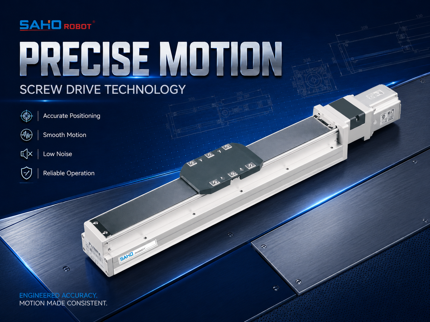
SDH Series is suitable for compact built-in linear motion where installation space needs careful planning.
| Product Direction | Best-Fit Situation | Before Inquiry |
| SDM Series | General screw drive axis for stable positioning, rigidity, and load support. | Prepare load, stroke, speed, repeatability, installation direction, and motor brand. |
| SDH Series | Built-in actuator for compact equipment and limited installation space. | Prepare envelope drawing, motor side, cable side, stroke, and service access notes. |
How to Choose Between SDM and SDH
Choose SDM as the starting point when the project needs a general screw drive axis with stable positioning and strong structure. It is often easier to review for standard automation layouts, fixture movement, vertical axes, and multi-axis systems. Model sizes can be compared around load, stroke, and installation direction.
Consider SDH when the machine envelope is tight. The built-in actuator structure may fit compact equipment better, especially when the axis must sit inside a narrow frame or under a protected machine cover. The layout should confirm motor clearance and maintenance space before final selection.
In either case, the product page should not replace an application review. A machine with the same stroke may still need a different model if load position, cycle time, vertical direction, or environmental conditions are different. SAHO should receive both specification values and layout information.
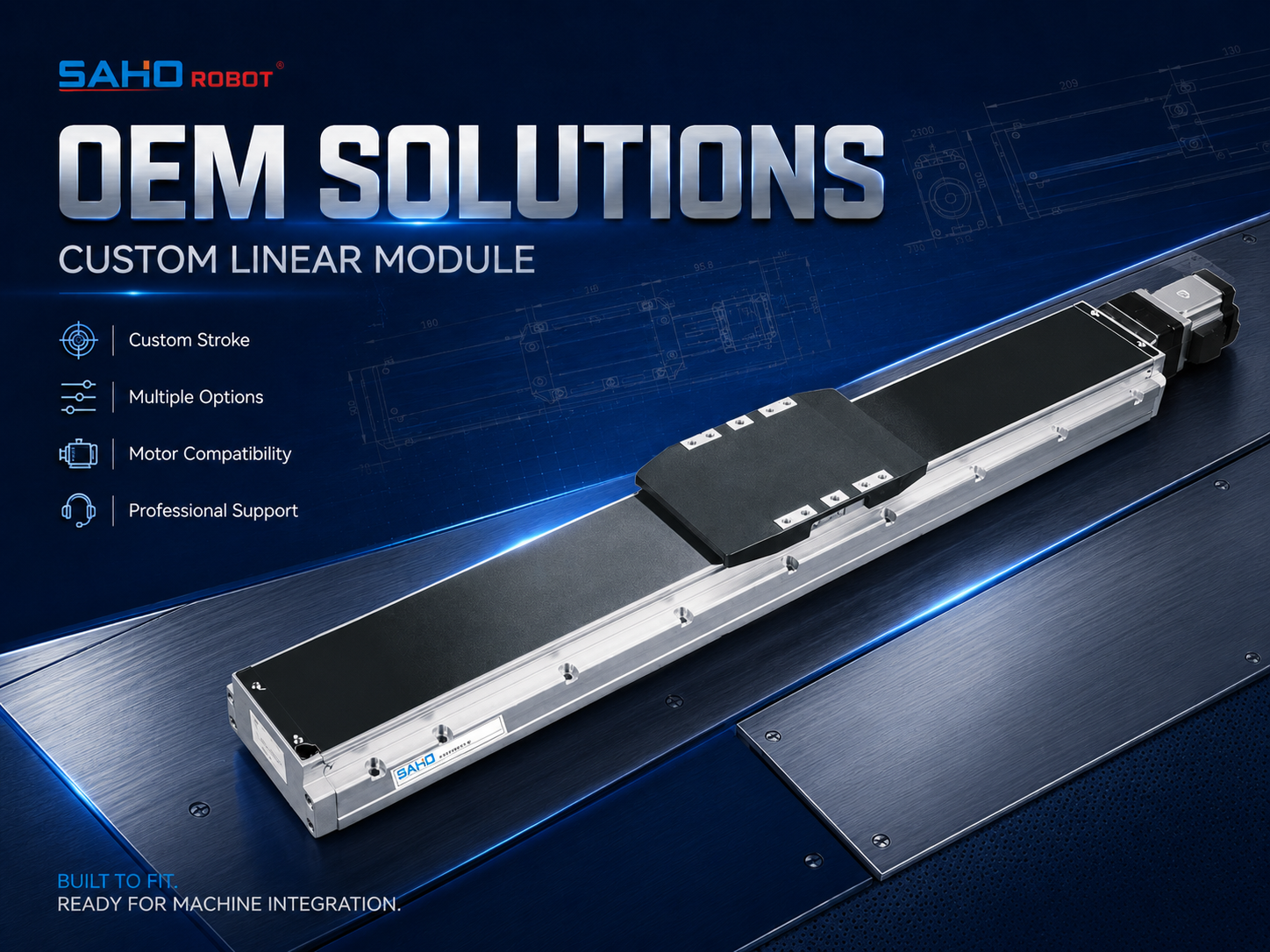
SDH Series can support space-limited layouts where motor side, cable routing, and access need early confirmation.
Common Selection Mistakes to Avoid
Selecting Only by Payload
Payload is important, but it is not enough. A light part can still create a large moment if the fixture extends away from the carriage. Offset distance and bracket height should be shared with the load value.
Process force may exceed the static payload. A probing, clamping, insertion, or light contact operation can push against the axis. Working force should be described separately when the process includes contact.
Requesting Speed Without Cycle Data
Maximum speed alone can be misleading. A short stroke may never reach the requested peak speed. Move distance, move time, dwell time, and acceleration should be reviewed together.
Aggressive acceleration may increase vibration and settling time. A smoother motion profile can sometimes improve the real process cycle. Practical cycle planning is more useful than a single high-speed value.
Ignoring Vertical Holding Requirements
Vertical applications should never be treated like simple horizontal motion. Gravity affects holding force, motor brake selection, and emergency stop behavior. Vertical axis data should include moving load, stopping requirement, and safety expectation.
A brake motor or mechanical holding method may be needed depending on the machine condition. The control method should match the real payload and screw lead, especially for Z-axis systems with tools or grippers.
Leaving Motor Interface Too Late
Motor interface decisions can change the actuator envelope. Flange size, shaft diameter, brake length, and cable direction can all affect the final installation. Motor brand and motor data sheet should be provided before the final drawing is released.
If the motor platform changes late, the adapter plate, total length, and cable path may need revision. Early motor confirmation helps keep procurement and assembly schedules stable.
Not Sharing Drawings Before Quotation
Text specifications cannot show every interference risk. The actuator may meet load and stroke requirements, but the motor may collide with a frame. A drawing review is valuable before a final quotation or order release.
Even a simple marked image can help. It should show axis direction, mounting face, motor side, workpiece location, and available length. This helps SAHO understand the machine situation faster.
Inquiry Path: From Application Data to Product Recommendation
A useful inquiry should make the next engineering step obvious. The message should not only ask for a model number. It should explain the motion task, machine layout, and selection limits.
A good inquiry may include application type, axis quantity, stroke, moving load, load position, speed, repeatability, installation direction, motor brand, and environment. A drawing file or sketch can reduce the need for repeated clarification.
| Step | Action | Expected Result |
| 1 | Define the motion task and application process. | The actuator direction becomes clear. |
| 2 | Prepare load, stroke, speed, repeatability, and duty cycle. | The model range can be narrowed. |
| 3 | Add mounting direction, motor brand, and environment notes. | The configuration can be reviewed more accurately. |
| 4 | Send 2D or 3D files for installation checking. | Interference and interface risks can be reduced. |
Recommended Data Format for Faster Review
To make the review faster, each axis can be described in the same format. This is especially useful for equipment with X, Y, and Z axes because it avoids mixing one axis condition with another.
| Axis | Example Data to Provide |
| X Axis | Stroke 800 mm, horizontal mount, carries Y axis plus tooling, target speed 500 mm/s. |
| Y Axis | Stroke 400 mm, horizontal mount, carries Z axis and fixture, repeatability target specified. |
| Z Axis | Stroke 150 mm, vertical mount, brake required, tool weight and center of gravity provided. |
The drawing should mark the motor side and cable side. These details may look small, yet they affect installation and wiring. Process notes should also include any contact force, dust, oil, powder, or unusual temperature so SAHO can review whether a standard structure is enough or whether protection and customization should be discussed.
FAQ
What parameters are needed to select a screw drive linear actuator?
The main parameters are load, stroke, speed, acceleration, repeatability, accuracy, duty cycle, mounting direction, and working environment. Motor brand, brake requirement, sensor layout, cable direction, and available drawing files should also be included because these details help match the axis to the real machine condition.
How is repeatability different from accuracy?
Repeatability means the axis can return to the same position again and again under similar conditions. Accuracy means the actual position matches the commanded position across the travel range. The correct requirement depends on how the process checks the motion result.
Can SAHO support custom stroke or motor mounting?
Yes. SAHO can review custom stroke, motor mounting direction, sensor position, installation interface, dust cover needs, and multi-axis structures according to project data. Custom planning requires clear stroke, load, speed, accuracy target, installation direction, motor details, and drawings.
When should SDM Series be considered?
SDM Series should be considered when the project needs a general screw drive axis for stable positioning, high repeatability, and higher load support. It can fit assembly equipment, inspection stations, battery equipment, vertical axes, and multi-axis positioning systems.
When should SDH Series be considered?
SDH Series should be considered when the machine needs compact built-in integration. It is useful when installation space is limited, the actuator must fit inside a narrow structure, or the machine requires a cleaner axis layout. Envelope drawings and service access should be checked before final selection.
Summary and Practical Next Steps
A good selection process starts with the application, not with a catalog code. Load, stroke, speed, repeatability, duty cycle, mounting direction, environment, motor brand, and drawing files should be clear before the final model is chosen. With this information, SAHO can review SDM Series, SDH Series, and the correct screw drive configuration with fewer assumptions.
Prepare total moving load, center of gravity, effective stroke, and target cycle time before asking for a model.
Confirm repeatability, accuracy, duty cycle, installation direction, environment, and motor brand before quotation.
Send 2D drawings, 3D files, or layout sketches so SAHO can check mounting space and possible interference.
For a practical recommendation, send SAHO the stroke, load, speed, required accuracy, repeatability target, installation direction, motor brand, and drawing files. With this data, the ball screw linear module can be selected around the real machine task rather than a rough product guess.
Send Application Data for SAHO Selection SupportShare stroke, moving load, load center, speed, repeatability, installation direction, motor brand, environment, and drawings. SAHO can help review SDM or SDH model direction based on the real machine layout. |







-
-
 English
 -
 Français
 -
 Deutschland
 -
 Italia
 -
 Polska
 -
 España
 -
 Русский язык
 -
 日語
日語 -
 한국
한국 -
 Türkiye
 -
 português
 -
 بالعربيةês
 -
 Tiếng Việt
 -
 คนไทย
คนไทย -
 简体中文
简体中文 -
繁體中文
-