
Date:2026-06-18 Click:485
Modern industrial automation relies on efficient, accurate, and reliable linear motion. Whether a machine is transferring products across a production line, positioning tooling, pressing components, lifting a fixture, or performing high-speed precision processing, the selected linear motion solutions directly influence productivity, stability, and long-term machine performance.
However, there is no single motion technology suitable for every application. Some machines need long-stroke, high-speed transfer. Others need precise positioning, stable thrust, or servo-controlled pressing. Advanced manufacturing equipment may require high-speed, high-response direct-drive motion. The best motion solution is not the most powerful one, but the one that best matches the application requirements.
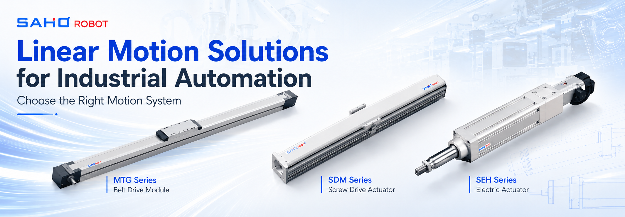
This guide explains how to select the right motion system for industrial automation by comparing MTG Series belt drive modules, SDM Series screw drive actuators, SEH Series servo electric cylinders, and MK Series linear motor products. It also explains how load, stroke, speed, mounting direction, process force, environment, and maintenance access affect final selection.
Quick Selection Guide for Industrial Automation
A useful selection process starts with the application, not with a catalog number. The table below gives a practical first direction for common automation tasks. Final model selection should still review load, stroke, speed, acceleration, duty cycle, mounting direction, and machine layout.
| Application | Recommended Product Direction | Main Reason |
| Material handling, packaging, tray transfer, pick and place, gantry robot | MTG Series Belt Drive Module | Long stroke, high-speed transfer, and flexible multi-axis integration |
| Precision positioning, dispensing, inspection, height adjustment, vertical motion | SDM Series Screw Drive Actuator | Stable positioning, repeatability, rigidity, and stronger thrust |
| Pressing, assembly, valve control, force-controlled motion, cylinder replacement | SEH Series Servo Electric Cylinder | Programmable force, position control, and cleaner servo-controlled pushing |
| Semiconductor equipment, laser processing, high-speed inspection, precision alignment | MK Series Linear Motor Product | High-speed, high-response direct-drive motion with fast dynamic performance |
Choose MTG Series for long-stroke and high-speed transfer.
Choose SDM Series for precise positioning and stable thrust.
Choose SEH Series for servo-controlled pushing and pressing applications.
Choose MK Series for high-speed, high-response direct-drive motion.
Start With the Motion Task, Not the Product Name
Every useful motion system decision starts with the movement itself. A transfer station may need long travel and stable speed. An inspection station may need smooth travel and low vibration. A press-fitting station may need short travel, strong thrust, and safe stopping. The process path should define the product family before any model is selected.
The moving axis does not only carry the workpiece. It also carries the gripper, fixture plate, sensor bracket, camera, light source, pneumatic tube, vacuum line, cable carrier, and adapter hardware. The real moving mass is often much higher than the part weight shown in a production document.
The process at the target position matters as much as the travel. A camera axis may carry little mass, but it may require low vibration and fast settling. A screw fastening head may move only a short stroke, but it creates reaction force at the tool tip. The selected axis must handle motion force and process force together.
For example, an Electronic Component Assembly machine may include feeding, vision alignment, precise placement, and final inspection. Each station may use straight-line motion, but the best axis for tray transfer may differ from the best axis for vertical placement. A complete machine often combines several motion technologies instead of forcing one structure into every position.
MTG Series Belt Drive Modules for Long Stroke and Fast Transfer
When long travel distances and fast transfer speeds are required, a belt drive module is often the preferred motion structure. The MTG Series is designed for high-speed automation applications that require long stroke, lightweight moving structure, and flexible installation options.
Compared with screw-driven systems, belt drive modules are often more practical for longer strokes and faster travel. They help transfer trays, move fixtures, feed workpieces, position inspection heads, and support gantry-style motion across a wide machine area.
The MTG Series is especially suitable for machines where cycle time and travel distance are more important than high thrust force. For large working areas, multiple belt drive modules can also be combined into XY, XYZ, or gantry motion systems.

SAHO MTG Series belt drive module for long-stroke transfer, feeding, scanning, and machine handling layouts.
Belt drive selection should still include payload, acceleration, moment load, cable routing, and frame stiffness. A long-stroke axis may carry a light workhead, but the cable carrier, bracket, sensor, and tooling can add hidden mass. The moving assembly should be listed completely before model choice.
SDM Series Screw Drive Actuators for Precision and Stable Thrust
Many industrial applications require stable positioning, controlled motion, and higher thrust. In these situations, a screw drive actuator often provides the best balance between precision and rigidity.
The SDM Series integrates the ball screw mechanism, carriage, guide rail, and mounting structure into a compact motion unit. Compared with belt drive modules, SDM screw drive actuators provide stronger positioning performance and higher thrust, making them suitable for precision automation tasks.
SDM Series can support dispensing equipment, precision assembly, inspection systems, height adjustment, vertical lifting, press-fitting assistance, and battery manufacturing equipment. It is especially useful when stable positioning directly affects product quality.

SAHO SDM Series screw drive actuator for precise positioning, controlled thrust, and compact automation axes.
Vertical screw axes require special attention because gravity changes the holding requirement during stops, alarms, or power loss. Brake planning, safe control logic, and mechanical stopping positions should be reviewed before the machine layout becomes fixed.
SEH Series Servo Electric Cylinders for Pressing and Controlled Force
Servo electric cylinders are increasingly replacing pneumatic and hydraulic cylinders in modern automation equipment. Unlike traditional cylinders that rely on air pressure or hydraulic systems, the SEH Series servo electric cylinder provides programmable motion with controlled speed, position, and thrust.
SEH Series can support press fitting, automatic assembly, valve control, welding equipment, packaging machinery, semiconductor equipment, medical equipment, and force-controlled applications. It is useful when a machine needs controlled push, lift, clamp, press, or adjustment motion.
Compared with pneumatic cylinders, servo electric cylinders can offer higher positioning accuracy, programmable motion profiles, adjustable force and speed, lower maintenance requirements, and better process consistency. This makes SEH Series suitable for machines that need repeatable force control and clean operation.

SAHO SEH Series servo electric cylinder for controlled pushing, lifting, pressing, clamping, and machine adjustment.
SEH Series should not be treated as a universal replacement for every linear axis. Fast multi-point transfer, large workspace motion, and high-speed gantry travel may still need module-based axes. The servo electric cylinder should match the task shape, force demand, stroke range, and control target.
MK Series Linear Motor Products for High-Speed Direct-Drive Motion
For applications requiring extremely fast response and outstanding dynamic performance, linear motor products provide an important motion option. The MK Series uses direct-drive linear motor technology to generate motion through electromagnetic force without belts or screws.
This direct-drive structure reduces mechanical transmission losses and supports excellent acceleration, fast settling time, smooth motion, and high dynamic response. MK Series can fit semiconductor equipment, laser processing machines, electronics manufacturing, lithium battery production, optical measurement equipment, and high-speed positioning platforms.
The full advantages of linear motor products can only be achieved when the machine also has a rigid structure, high-resolution feedback, stable installation platform, proper cable management, and suitable servo tuning. A weak machine frame can reduce the benefit of high-response direct-drive motion.

SAHO MK Series linear motor products for high-response precision motion, inspection, laser processing, and advanced automation sections.
Linear motor products belong to a separate direct-drive category, while belt drive modules, screw drive actuators, and servo electric cylinders belong to module or actuator-based motion solutions. This distinction helps engineers keep product categories clear while still building a mixed motion system when the application requires it.
Comparing Different Motion Technologies
| Feature | MTG Belt Drive Module | SDM Screw Drive Actuator | SEH Servo Electric Cylinder | MK Linear Motor Product |
| Stroke length | Excellent | Good | Medium | Excellent |
| Travel speed | High | Medium | Medium | Very high |
| Positioning accuracy | Good | Excellent | Excellent | Excellent |
| Thrust force | Medium | High | Very high | High |
| Best application | Transfer and handling | Precision positioning | Pressing and assembly | High dynamic motion |
Important Design Considerations Before Selection
Before selecting a motion system, engineers should evaluate stroke length, usable travel, payload, center of gravity, speed, acceleration, required accuracy, repeatability, mounting orientation, environment, duty cycle, cable routing, and maintenance access.
Load should include every item that moves: fixture, tool, adapter plate, workpiece, moving cables, sensor brackets, tube holders, fasteners, and upper-axis components. A module can meet the payload number and still vibrate if acceleration, overhang, or process force is ignored.
Moment load deserves special attention. A lightweight tool mounted far from the carriage center can generate significant moment load and reduce system stability. Tooling shape, mounting position, and process force should always be reviewed together with payload.
Mounting direction also changes selection logic. Horizontal axes mainly handle moving mass and acceleration force. Vertical axes must also lift, hold, and stop safely under gravity. Brake planning, emergency behavior, and falling-load risk should be reviewed before the final axis choice.
Cable routing belongs inside the selection process. Moving cables and tubes add drag, weight, and service risk. A tight bend radius can shorten cable life, while a loose tube can rub against covers or disturb motion stability. The cable path should be checked together with the actuator layout.
Build the Right Motion System
Modern automation machines often combine different motion technologies to achieve the best overall performance. A single machine may use an MTG belt drive module for long transfer, an SDM screw drive actuator for precise positioning, an SEH servo electric cylinder for pressing force, and an MK linear motor product for ultra-fast inspection or alignment motion.
This mixed architecture can improve performance without overcomplicating every axis. Long travel does not always need the same technology as precision pressing. High-speed inspection does not need to replace every belt or screw axis in the equipment. Each axis should be chosen for its real task.
The right motion system balances travel distance, speed, thrust, accuracy, response, machine stiffness, service access, and cost. The goal is not to choose the strongest product everywhere. The goal is to match the motion technology to the process requirement and build equipment that remains stable during real production.
Practical Axis Selection Checklist
Application Information
Process type: transfer, feeding, dispensing, inspection, pressing, loading, unloading, measuring, or assembly.
Motion layout: single axis, XY, XZ, XYZ, gantry, side-mounted axis, or special machine structure.
Workpiece information: size, weight, contact condition, and position during movement.
Tooling information: gripper, fixture, camera, nozzle, spindle, screw head, sensor, or process head.
Process force: pressing force, insertion load, fastening reaction, probing force, or clamping force.
Motion Information
Stroke: working travel, reserve travel, home position, safety space, and mechanical limit distance.
Speed: target travel speed and actual process speed.
Acceleration: acceleration, deceleration, allowed vibration, and settling time.
Accuracy: repeat position, smooth velocity, straightness, and absolute positioning need.
Duty cycle: moves per minute, daily operating hours, and production rhythm.
Installation Information
Mounting direction: horizontal, vertical, side-mounted, inverted, angled, or overhung.
Frame condition: base plate thickness, support span, mounting flatness, and available fastening points.
Space limit: machine footprint, guard position, access door, and maintenance clearance.
Cable path: cable carrier space, bend radius, fixed end, moving end, and tube routing.
Environment: dust, oil mist, adhesive, heat, clean area, coolant, or other process exposure.
FAQ
How should a belt drive module and screw drive actuator be compared?
The application should set the comparison. Belt drive modules usually suit long strokes and faster transfer. Screw drive actuators usually suit controlled positioning, stronger thrust, and more rigid movement. Stroke, load, speed, accuracy, and process force should be checked together.
When does a servo electric cylinder make sense?
A servo electric cylinder makes sense when a machine needs programmable pushing, pressing, lifting, clamping, or force-controlled motion. It is often selected when pneumatic motion is too rough or when adjustable force, speed, and position are required.
Why are linear motor products treated as a separate category?
Linear motor products use direct-drive motion instead of belt, screw, or cylinder transmission. They are selected for high-speed, high-response precision motion, but they require suitable machine stiffness, feedback, tuning, and cable management.
Can one machine combine MTG, SDM, SEH, and MK products?
Yes. A mixed motion system can be practical. MTG may handle long travel, SDM may handle precision positioning, SEH may control pressing force, and MK may support high-speed inspection or alignment. The product mix should reflect the actual station requirements.
What information helps SAHO review a motion application?
Useful information includes stroke, load, speed, acceleration, mounting direction, duty cycle, required repeat position, process force, tool offset, and environment. A sketch of tooling offset, cable direction, and frame position also helps the review.
Conclusion: Choose the Motion Solution That Matches the Application
Selecting the right linear motion solution begins with understanding the application. MTG Series is ideal for long-stroke and high-speed transfer applications. SDM Series provides stable positioning and higher thrust for precision automation. SEH Series servo electric cylinders deliver programmable force and motion control for pressing, lifting, and adjustment tasks. MK Series linear motor products offer high-speed, high-response direct-drive motion for advanced manufacturing equipment.
By evaluating motion requirements, environmental conditions, machine layout, and production goals, engineers can select the most suitable motion technology and build automation systems that deliver reliable performance for years to come.
Choose MTG Series for long-stroke and high-speed transfer.
Choose SDM Series for precise positioning and stable thrust.
Choose SEH Series for servo-controlled pushing and pressing applications.
Choose MK Series for high-speed, high-response direct-drive motion.
The best motion solution is not the most powerful one, but the one that best matches the application requirements. For a project that needs a finished linear robot or complete motion system, SAHO Robot can review the application path and match suitable product combinations for factory automation.


-
-
 English
 -
 Français
 -
 Deutschland
 -
 Italia
 -
 Polska
 -
 España
 -
 Русский язык
 -
 日語
日語 -
 한국
한국 -
 Türkiye
 -
 português
 -
 بالعربيةês
 -
 Tiếng Việt
 -
 คนไทย
คนไทย -
 简体中文
简体中文 -
繁體中文
-