
Date:2026-06-02 Click:132
In modern automation equipment, one motion axis rarely solves the whole process. A station may need long transfer, side positioning, vertical lifting, tooling approach, inspection, and unloading inside one machine frame. Therefore, a linear belt actuator layout should connect motion performance with structure, timing, payload balance, service access, and future maintenance.
Finished belt-driven linear modules help simplify machine design because they provide a defined body, carriage, belt drive structure, motor interface, sensor area, and mounting surface. As a result, machine builders can create cleaner layouts, reduce custom assembly work, and improve repeatability across similar automation stations.
Application Value in Multi-Axis Automation
Multi-axis automation needs more than a fast single stroke. A production station may move a tray along an X-axis, shift it sideways on a Y-axis, and lower a tool on a Z-axis. Therefore, the overall layout must support timing, stiffness, payload balance, safe motion paths, and maintenance access.
In long-stroke transfer, belt-driven linear modules offer a practical balance between speed and travel distance. They can move parts, carriers, fixtures, or tooling across a wide area without turning the machine into a complex linkage system. The compact module body also helps keep the motion path cleaner and easier to mount.
The best layout depends on the role of each axis. A base transfer axis may carry several upper axes and the full moving assembly. A side axis may carry a vertical unit and an offset tool. Consequently, the load path changes with every added module, so the full moving mass must be reviewed before model selection.
Why Belt-Driven Actuators Are Commonly Used in Multi-Axis Systems
As automation equipment becomes larger and faster, engineers often need motion systems that cover longer travel distances without making the machine structure too complex. Belt-driven linear actuators are commonly used in this situation because they support high-speed motion, long stroke capability, lightweight moving structures, and flexible installation in Cartesian and gantry systems.
For applications that require travel over a wide working area, a belt drive module can be more practical than building a motion axis from separate belts, pulleys, guides, and custom mounting parts. The module format helps keep the motor, pulley, carriage, linear support structure, sensor area, and mounting surface in one organized package.
However, long travel alone does not define the correct model. Stroke, speed, acceleration, payload, moment load, mounting direction, duty cycle, and service space all affect the final selection. A long axis should be selected from the full application profile, not only from the travel length.
Common Multi-Axis Layouts: XY, XYZ, and Gantry Systems
XY Positioning Systems
An XY positioning system combines two linear actuators mounted perpendicular to each other. The X-axis usually provides the main horizontal travel, while the Y-axis provides transverse positioning. This layout is common in vision inspection equipment, dispensing systems, labeling equipment, product positioning stations, and light-duty pick-and-place machines.
In an XY layout, the lower axis must carry the upper axis and the payload. Therefore, the base axis should be checked carefully for moving mass, offset load, acceleration demand, and machine-frame stiffness.
XYZ Cartesian Systems
Adding a vertical Z-axis creates a complete three-dimensional positioning system. XYZ systems are widely used in automated assembly, loading and unloading stations, packaging automation, robotic handling, and machine tending applications.
Because the Z-axis typically carries the end effector and payload, designers should minimize moving mass while keeping enough rigidity. The horizontal belt module must carry the vertical unit, motor mass, brake components, adapter plates, grippers, sensors, and cables.
Gantry Robot Layouts
For larger workspaces, gantry systems provide wider coverage and better support for long-travel automation. A typical gantry robot includes two parallel X-axes, a moving Y-axis beam, and a vertical Z-axis assembly.
Gantry layouts are often used in palletizing systems, logistics automation, sheet handling equipment, warehouse automation, inspection platforms, and large-format manufacturing systems. Both parallel axes must remain synchronized to avoid beam twist during homing, acceleration, travel, deceleration, and emergency stop.
Speed, Stroke, and Cycle Time Planning
Speed should be reviewed with stroke length. A short move may never reach maximum speed because acceleration and deceleration take most of the motion time. A real cycle calculation should include travel distance, acceleration, deceleration, dwell time, and settling time.
Long travel may benefit more from higher allowable speed. A shuttle moving trays across several process points can reduce idle time if the axis accelerates smoothly and stops cleanly. However, high speed without enough structural stiffness can create vibration and increase waiting time before the next process step.
Takt time is not only a motor issue. The machine frame, carriage load, tool bracket, cable chain, and control tuning all influence real output. A fast move that requires a long wait before inspection or gripping may not improve production flow.
Payload, Moving Mass, and Center of Gravity
Payload should include every part that moves with the carriage. This includes the workpiece, fixture, tool plate, gripper, vacuum unit, camera mount, cables, fittings, sensors, adapter plates, and upper axes. A complete moving-mass list should be prepared before model selection.
The center of gravity is just as important as total mass. A load placed near the carriage center behaves differently from a load that sits far outside the carriage footprint. The longer the offset, the larger the moment load becomes.
Moment load affects repeatability, vibration, and wear. During acceleration, an offset load can twist the carriage and stress the support structure. Over time, this may increase noise, shorten service life, or reduce stop stability.
Choosing Between Standard and Wide-Body Belt Actuators
Standard-Profile Belt Actuators
Standard-profile belt actuators are often selected for compact machines, moderate payloads, limited installation space, and general automation equipment. Their lightweight structure helps support high-speed movement while keeping the overall machine size controlled.
This type of actuator is suitable when the tool is reasonably centered, the payload is not heavily offset, and the application requires fast transfer rather than high moment-load resistance.
Wide-Body Belt Actuators
Wide-body belt actuators provide additional structural support and better resistance to moment loads. They are often selected for long-span gantry systems, larger tooling assemblies, heavier payloads, high-speed systems requiring enhanced stability, and applications with offset brackets or wide adapter plates.
The wider support structure helps distribute load more evenly and maintain smoother motion under demanding operating conditions. In many multi-axis projects, choosing the correct actuator profile improves performance more effectively than simply increasing motor power.
TR64 Belt Actuator for Compact Multi-Axis Automation
For compact multi-axis automation, TR64 provides a relevant product path for high-speed linear motion and flexible installation. It can be considered for packaging equipment, inspection systems, pick-and-place automation, product positioning stations, and small to medium Cartesian robot layouts.
TR64 is especially suitable when the application needs long-stroke transfer, controlled moving mass, and a cleaner module format. In an XY or XYZ system, it can serve as a horizontal transfer axis or as part of a compact positioning platform.

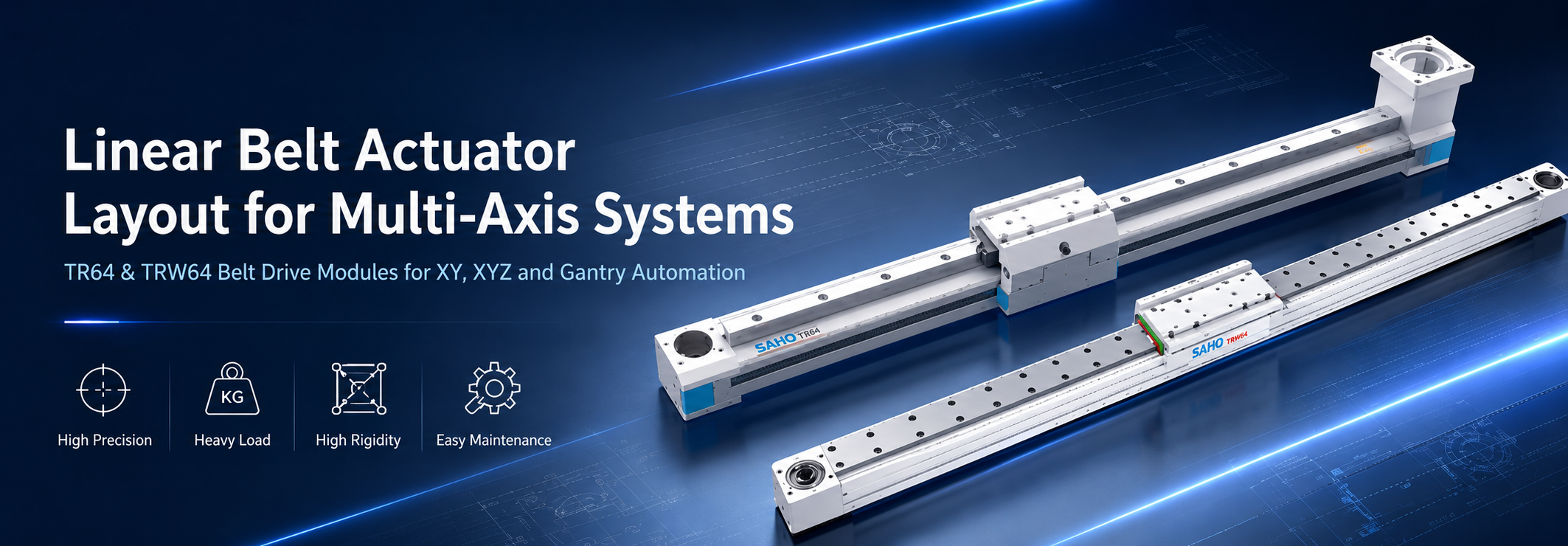
TR64 belt drive linear module for compact multi-axis automation, long-stroke transfer, shuttle movement, and horizontal axis layouts.
TRW64 Wide Belt Actuator for Gantry and Moment-Sensitive Layouts
For gantry structures and moment-sensitive layouts, TRW64 provides a wider structural design to improve rigidity and load-carrying stability. It is suitable for long-travel transfer systems, larger automation equipment, crossbeam layouts, and applications with higher moment loads.
TRW64 is especially useful when the application includes wide tools, overhung tooling, camera bars, larger adapter plates, or paired-axis gantry structures. The wider body helps support the moving assembly more steadily and reduces the risk of vibration caused by offset loads.

TRW64 wide belt module for gantry robots, long-travel transfer systems, overhung tooling, and moment-sensitive multi-axis layouts.
Belt Tension, Pulley Alignment, and Motion Quality
Belt tension has a direct effect on motion quality. Too little tension can reduce repeatability and create unstable response. Too much tension can increase bearing load and reduce service life.
Tension should follow the recommended method for the selected module. Initial checks after early operation can also help because mechanical parts may settle after commissioning. A planned inspection schedule is better than waiting for noise or position variation.
Pulley alignment controls belt tracking. Misalignment can cause edge wear, heat, noise, or uneven belt behavior. In a multi-axis system, this issue may appear at the tool tip rather than directly at the belt.
Cable-chain layout should also be checked. A poorly routed cable chain can pull the carriage sideways during travel. Over time, this can increase friction, reduce smoothness, and make tuning more difficult.
Pairing Horizontal Belt Modules With Vertical Axes
Many automation systems pair a long horizontal belt module with a vertical motion unit. This structure appears in pick-and-place, tray loading, panel handling, inspection, packaging, and process approach systems. The horizontal axis moves across the work area, while the vertical axis raises or lowers the tool.
The horizontal axis must carry the vertical unit and its complete tooling. This includes motor mass, brake components, adapter plates, grippers, sensors, and cables. Therefore, the horizontal payload calculation should include the full vertical assembly.
For vertical-axis planning, the ZTM Series vertical-axis product page can serve as a relevant internal reference. It should be used as a vertical pairing option, while the main belt-drive product path remains TR Series.
Application Scenarios in Industrial Lines
In packaging automation, repeated shuttle motion is common. Cartons, pouches, bottles, carriers, or grouped products may need movement between operations. Belt-driven modules can support fast transfer while keeping the layout relatively clean.
In material handling and loading stations, belt actuators can move trays, panels, fixtures, or carriers between process points. The layout should consider working area, stroke length, station spacing, sensor position, and service access.
In vision inspection, smooth stop behavior is critical. A camera can only capture reliably after vibration is controlled. Module selection should consider settling time, bracket stiffness, frame rigidity, and cable routing.
For large-format production-line motion, the Solar Energy application page can support internal reading where wide handling and panel-related automation are relevant.
Selection Factors for Belt Drive Module Layout
| Selection Factor | Why It Matters | Practical Check |
| Working area | Defines motion envelope and axis arrangement. | Confirm travel distance, station spacing, and future expansion needs. |
| Payload and moving mass | Affects acceleration, motor sizing, and belt load. | Count workpieces, tools, fixtures, sensors, cables, and upper axes. |
| Moment load | Controls vibration, rigidity demand, and service life. | Check offset tools, wide brackets, and worst-position center of gravity. |
| Cycle time | Determines required acceleration and duty demand. | Include move time, dwell time, and settling time. |
| Actuator profile | Standard and wide-body structures suit different load conditions. | Use standard profiles for compact axes and wide-body profiles for gantry or moment-sensitive layouts. |
| Maintenance access | Reduces downtime during inspection and adjustment. | Reserve access to belts, sensors, fasteners, and cable chains. |
Best Practices for Multi-Axis System Design
Minimize moving mass: lighter tools, brackets, and cable layouts can improve acceleration and reduce motor demand.
Select enough rigidity: actuator profile, carriage support, and machine-frame stiffness should match the payload and moment load.
Plan cable management early: cable carriers should not pull the carriage sideways or block maintenance access.
Allow service clearance: belt tension, fasteners, sensors, motors, and cable chains should remain accessible after guards are installed.
Review future expansion: if tooling or working area may increase later, leave enough structure and space for future adjustment.
Common Selection Mistakes
Underestimating moving mass: tooling, adapters, cables, and upper axes add weight quickly.
Ignoring center of gravity: an offset load can create deflection, vibration, or uneven wear.
Choosing only by speed: a fast axis can still reduce output if the tool shakes after stopping.
Using a standard profile where wide support is needed: gantry beams and overhung tooling may require a wider actuator body.
Forgetting service access: guards and nearby equipment can block belt, sensor, motor, or cable-chain inspection.
FAQ
Why are belt-driven actuators common in multi-axis automation?
Belt-driven actuators are commonly used because they support high-speed motion, long stroke capability, lightweight moving structures, and flexible integration into XY, XYZ, and gantry systems.
When should TR64 be considered?
TR64 can be considered for compact multi-axis systems, packaging equipment, inspection systems, pick-and-place automation, product positioning stations, and small to medium Cartesian robot layouts.
When is TRW64 a better choice?
TRW64 is a better choice when the system needs a wider support structure, higher rigidity, improved moment-load resistance, or better stability for gantry structures and overhung tooling.
What should be checked before selecting a belt actuator for a gantry system?
Check working area, payload, moving mass, moment load, crossbeam stiffness, synchronization method, homing sequence, cable management, and maintenance access.
Can one belt module size cover every axis?
One size may cover several similar axes in a standardized machine. However, base transfer, side correction, vertical lift, and gantry motion often face different forces. Each axis should be selected by its role.
Why does vertical mounting need special review?
Vertical mounting adds gravity load to the application. Brake function, holding force, power-off behavior, and emergency stop response need review. A vertical axis should not be selected by horizontal transfer rules alone.
Conclusion and Next Step
The success of a multi-axis automation system depends heavily on mechanical layout and actuator selection. Working area, payload, moving mass, rigidity, moment load, cycle time, synchronization, cable routing, and maintenance access all affect long-term performance.
For high-speed industrial automation, TR Series belt-driven linear modules provide a focused product path for XY systems, XYZ Cartesian robots, gantry structures, long-stroke transfer, and moment-sensitive layouts. For vertical-axis pairing, ZTM Series can be reviewed as a separate vertical motion option.


-
-
 English
 -
 Français
 -
 Deutschland
 -
 Italia
 -
 Polska
 -
 España
 -
 Русский язык
 -
 日語
日語 -
 한국
한국 -
 Türkiye
 -
 português
 -
 بالعربيةês
 -
 Tiếng Việt
 -
 คนไทย
คนไทย -
 简体中文
简体中文 -
繁體中文
-