

Date:2026-05-27 Click:475
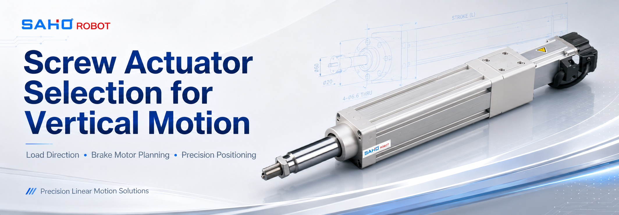
Vertical motion looks simple from the outside, yet it places very different demands on a motion axis. Gravity acts during lifting, stopping, homing, alarm recovery, and power-off conditions. Therefore, a vertical screw actuator selection should begin with load direction, brake motor planning, stroke margin, accuracy needs, and maintenance access.
In industrial automation, a vertical electric actuator may lift a fixture, lower a test head, position a camera, move a dispensing valve, or support a compact pressing station. Meanwhile, a poor selection can cause drift, vibration, overload, unstable height, and difficult service. This article explains how to approach vertical motion selection around real machine use, not only around catalog figures.
Vertical Motion Starts With Gravity
First, vertical motion differs from horizontal motion because the load always works against the drive. In a horizontal axis, friction, acceleration, travel distance, and external force often decide the size. However, in a vertical axis, gravity remains active even when the machine stops.
As a result, holding force matters as much as moving force. A lifting head may move smoothly during trial operation, yet still drift after power loss. Therefore, vertical planning should include brake motor layout, torque margin, safe stop behavior, and restart logic.
In many machines, the moving mass includes more than the workpiece. For example, the actuator may carry a gripper, camera bracket, sensor plate, vacuum cup, tooling head, cable chain, hose set, and mounting hardware. Moreover, the center of gravity may sit away from the actuator centerline.
Because of this, selection should treat the moving assembly as one complete load. The load calculation should include mass, acceleration, cable drag, hose stiffness, process contact, and mounting angle. In other words, the hardest motion condition should define the selection baseline.
Additionally, vertical motion affects cycle timing in a different way. The downward stroke may appear easy because gravity assists movement. Nevertheless, the upward stroke decides motor torque, heat, acceleration limit, and long-term operating margin.
Therefore, a compact finished electric actuator can reduce layout risk. The motion unit brings the drive structure, body, output connection, and motor interface into one coordinated assembly. Consequently, the machine design can focus on safe lifting, clean installation, and repeatable operation.
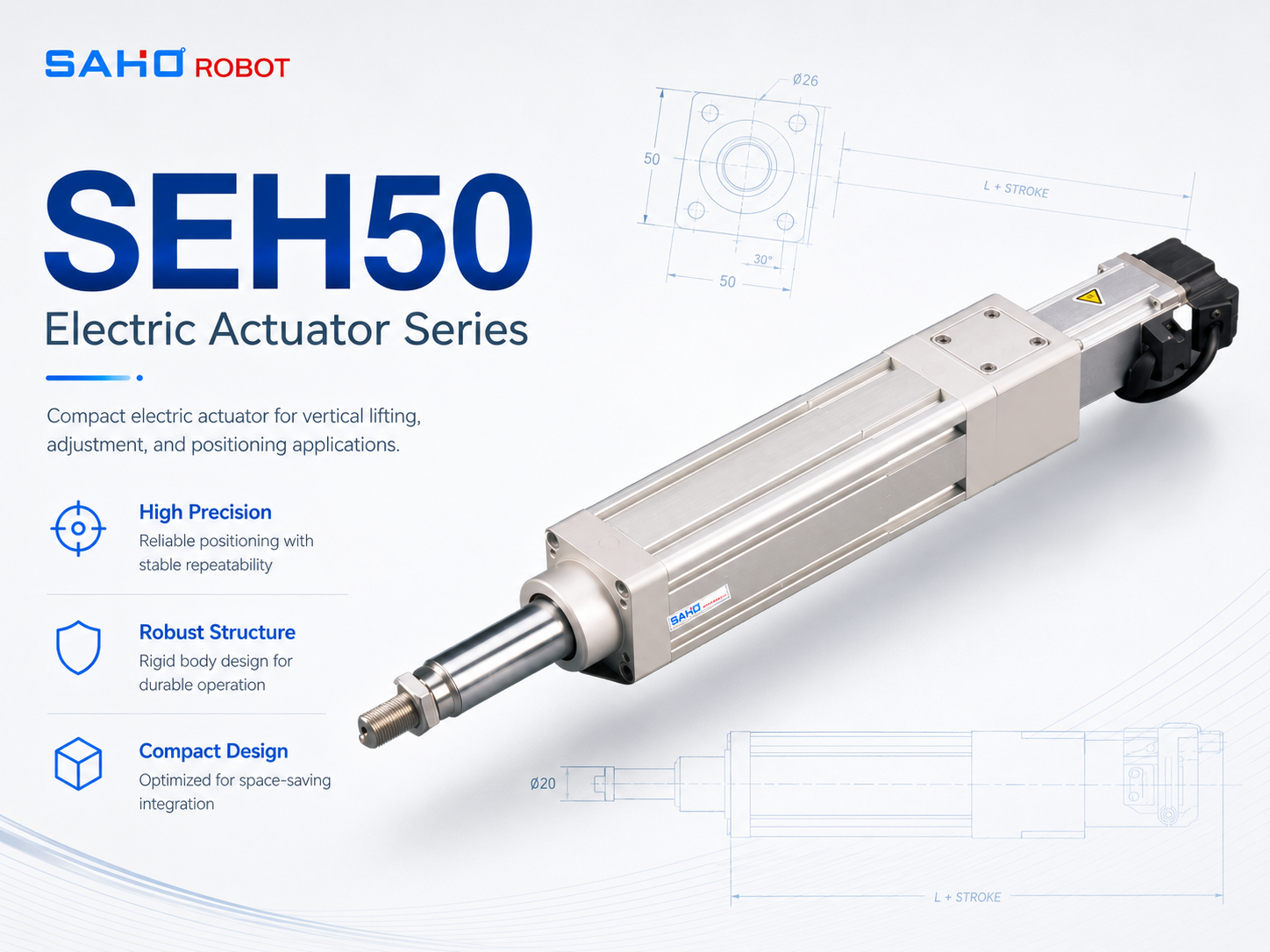
SAHO SEH50 Electric Actuator Series for compact vertical lifting, adjustment, and positioning layouts.
Why a Finished Electric Actuator Works Well for Vertical Axes
A finished electric actuator gives more than linear travel. It converts motor rotation into controlled motion and packages the support body, moving output, drive structure, and motor mounting interface into a usable automation axis. Therefore, it reduces the need to assemble many separate motion components.
This packaged approach is valuable in vertical motion. Gravity can expose weak alignment, loose fastening, and low frame stiffness quickly. As a result, a stable actuator body can improve installation consistency and reduce tuning difficulty.
Moreover, a finished module approach can support repeat equipment builds. When one actuator family appears across several machine stations, drawings, mounting plates, motor settings, maintenance notes, and spare part planning become easier to manage.
However, the actuator should not be treated as a standalone solution for every problem. The frame, brake motor, sensor layout, controller logic, mechanical stop, and service access still affect the final result. Therefore, the complete system should remain part of the selection discussion.
For example, a strong actuator mounted on a thin plate may still vibrate during fast lifting. Likewise, an accurate ball screw drive may still produce inconsistent height if the bracket bends under process force. Consequently, actuator choice and machine structure should be reviewed together.
In addition, the motion profile should match the mechanical structure. A smoother acceleration curve can reduce shock, noise, and settling time. Therefore, a well-selected actuator should also be paired with reasonable controller settings.
Where SAHO SEH Series Fits in Vertical Motion
The SAHO SEH Series is an electric actuator family for finished linear motion use. It includes models such as SEH50, SEH50L, SEH50T, SEH65, SEH65L, SEH65T, SEH80, and SEH80T. Therefore, it fits projects that need a complete actuator or motion unit rather than loose mechanical sourcing.
In compact machines, smaller SEH models can support short vertical strokes, light tooling movement, height adjustment, inspection head travel, and small fixture lifting. Meanwhile, larger SEH models can enter the discussion when the application requires stronger structure, longer travel, or higher load margin.
Additionally, rod-supported versions can help when the moving end needs a clear output structure. This can be useful for pushing, lowering, lifting, or presenting tooling to a work area. Still, side force should be controlled by the surrounding machine frame.
The SEH Series is especially relevant when the design goal is a clean actuator body with clear mounting and motor integration. As a result, it can simplify layout work in assembly machines, inspection stations, packaging equipment, and compact vertical positioning systems.
At the same time, model selection should still follow real working conditions. Load mass, stroke, speed, mounting direction, process force, and duty cycle should be reviewed before deciding a size. Otherwise, an axis may look correct on paper but struggle in production.
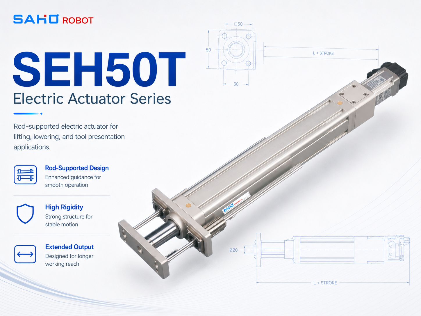
SAHO SEH50T Electric Actuator Series for rod-supported lifting, lowering, and tool presentation layouts.
Load, Stroke, Speed, and Accuracy Checks
First, load should be separated into static load, moving load, and process load. Static load describes what the actuator must hold at rest. Moving load adds acceleration and deceleration. Process load appears when a tool contacts, presses, probes, or clamps a part.
Next, stroke should include more than visible work travel. A vertical axis may need approach distance, working distance, retract distance, sensor clearance, and reserve travel. Therefore, the selected stroke should not force the machine to work near the mechanical end.
Speed also needs careful review. A high downward speed may reduce cycle time, but gravity can increase stopping stress. Meanwhile, a high upward speed increases motor demand and may raise heat during repeated cycles.
Accuracy should match the process. For example, a pick position may need stable clearance. A camera station may need repeatable focus height. A dispensing or probing station may need controlled final approach and low vibration.
Moreover, acceleration can be more important than top speed. A short move with sharp acceleration can create high peak load. Consequently, the motion profile should be checked together with mass, stroke, and duty cycle.
| Selection item | Why it matters | Practical check |
| Moving mass | It sets lifting torque and holding force. | Include tooling, brackets, wires, hoses, and fasteners. |
| Load direction | Gravity changes stop and restart behavior. | Size around upward motion and safe holding. |
| Stroke | Extra travel protects tooling and sensors. | Add approach, work, retract, and reserve distance. |
| Speed | Fast motion raises heat and stopping stress. | Use realistic acceleration and deceleration settings. |
| Accuracy | Height repeatability affects process quality. | Match precision to inspection, pressing, dispensing, or handling needs. |
| Brake planning | Power loss can cause downward motion. | Review brake motor, mechanical stop, and restart logic. |
Finally, the controller should support safe homing and recovery. A vertical axis may stop in the middle of travel after an alarm. Therefore, restart logic should avoid sudden downward movement and should confirm the machine state before motion resumes.
Brake Motor Planning and Anti-Drop Logic
For vertical installation, brake planning should appear early in the design review. A brake motor or mechanical lock helps prevent gravity drop when the axis stops or loses power. Therefore, it should not be added only after machine testing reveals drift.
The brake does not replace correct sizing. Instead, it holds the load when the machine stops, alarms, or powers down. Meanwhile, the motor and drive still need enough torque for lifting, controlled travel, acceleration, and deceleration.
A safe release sequence matters. The motor should build holding torque before the brake releases. Otherwise, the load may drop slightly before motion begins, which can damage parts or create position error.
Likewise, the stop sequence should protect the brake. The axis should decelerate under control before the brake clamps. If the brake repeatedly acts as the main dynamic stopping device, wear can increase quickly.
Additionally, mechanical stops and safety supports should be part of the layout. A mechanical stop can limit travel beyond the safe range. For maintenance, a support block, lock pin, or service position may also be needed according to the machine safety plan.
In short, vertical safety depends on layers. The brake holds position, the motor controls motion, the sensor confirms location, the controller manages logic, and the mechanical structure limits risk. Consequently, reliable vertical motion is a system result.
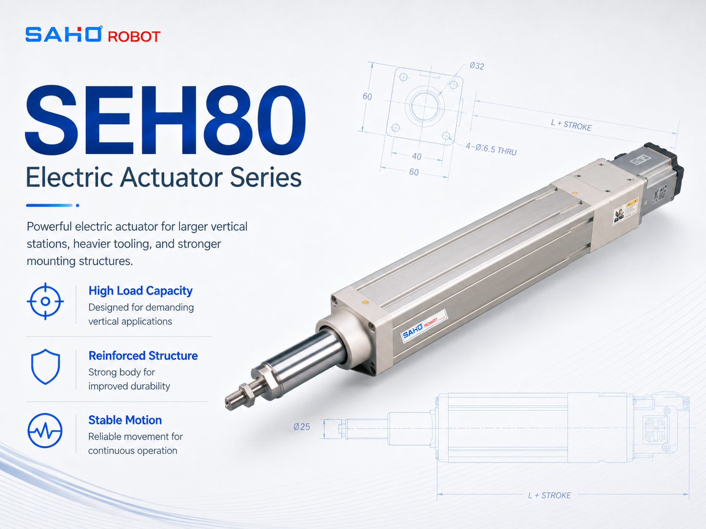
SAHO SEH80 Electric Actuator Series for larger vertical stations, heavier tooling, and stronger mounting structures.
Application Scenarios for Vertical Motion
In assembly equipment, vertical axes often move clamps, press heads, insertion tools, nests, and small positioning blocks. Therefore, smooth travel and stable stop behavior can directly affect part quality.
In inspection machines, the actuator may move a camera, sensor, light source, or probe. Moreover, different product models may require different working heights. A programmable electric actuator can support recipe-based adjustment and reduce manual changeover work.
In electronics testing, vertical movement may control contact between a probe head and a circuit board. Too much impact can damage pins, while poor repeatability can create false failures. Consequently, controlled final approach is more valuable than maximum speed.
In medical and laboratory automation, compact design and predictable movement are important. Sampling heads, dosing mechanisms, lifting tables, and optical inspection devices can all need repeatable vertical travel. In addition, a finished actuator body can help keep the equipment layout clean.
In packaging equipment, vertical motion can lift stacks, set height, move push-down heads, or position gates. Although the load may be moderate, the cycle count can be high. Therefore, maintenance access and brake behavior still matter.
In battery, solar, display, and automotive-related equipment, vertical axes may support transfer, inspection, pressing, positioning, or clamping. Each station has a different load and process force. As a result, copying one axis size across every station can create problems.
Compact Lifting and Height Adjustment
Compact lifting often appears in sensor positioning, focus adjustment, small clamp movement, and light fixture travel. The moving mass may be small, but the expected repeatability can be strict. Therefore, a compact actuator with clean mounting can be more suitable than an oversized structure with extra overhang.
Pressing, Clamping, and Tool Approach
Pressing and clamping tasks need careful force review. The actuator may lower the tool, yet the machine frame should carry reaction force. Otherwise, frame bending may appear as poor repeatability, uneven contact, or unstable pressure.
Inspection, Dispensing, and Probing
Inspection, dispensing, and probing often benefit from two-stage movement. A fast approach saves time, while a slower final move protects the part and improves process control. Consequently, the actuator should support smooth speed changes and stable stopping.
Matching SEH Series With Related SAHO Motion Products
For enclosed electric actuator layouts, the SEH Series is the main product path for this topic. It supports clean integration when the machine needs a finished actuator body for lifting, positioning, or tool presentation.
However, some machines need a module-style format with a different carriage layout or mounting approach. In those cases, the SDH Series can be reviewed as a related screw drive module option. The better choice depends on stroke, load center, installation direction, and machine structure.
Additionally, a complete automation cell may combine several motion products. One station may use a compact vertical actuator, while another station may use a wider module for transfer. Therefore, product matching should consider the full motion chain.
A larger model is not always the best answer. Sometimes a smaller actuator mounted on a strong frame works better than a larger actuator mounted on a weak plate. Consequently, stiffness and load center should be reviewed before increasing size.
Motor direction and cable exit should also be checked early. Vertical axes often sit inside compact frames, above conveyors, near covers, or close to fixtures. As a result, space for wiring, motor access, and future replacement should remain visible in the layout.
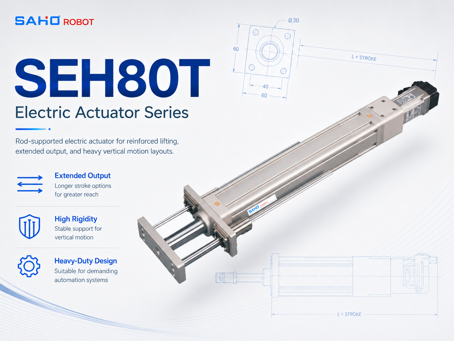
SAHO SEH80T Electric Actuator Series for reinforced lifting, extended output, and heavier vertical motion layouts.
Brake, Motor, Sensor, and Controller Pairing
A vertical actuator does not work alone. The motor, brake, driver, controller, sensor, and safety circuit all influence performance. Therefore, mechanical selection should happen with electrical and control planning.
First, the motor should cover the upward move with margin. It should also support acceleration and any process force. Moreover, the motor should stay within a reasonable thermal range during repeated cycles.
Next, the brake should match the holding condition. A holding brake keeps the axis in position during stop states. However, it should not become the normal high-speed stopping method.
Sensor placement also deserves careful planning. A home sensor, upper limit, lower limit, and ready signal can reduce wrong-position events. Meanwhile, the controller can prevent downward movement when the surrounding station is not ready.
For multi-axis machines, interlocks are important. The vertical axis should not descend while a horizontal axis remains in the wrong position. Similarly, the gripper, clamp, or fixture should confirm status before vertical movement begins.
In addition, alarm recovery should be clearly defined. A machine may stop mid-stroke with a load attached. Therefore, restart logic should confirm brake state, motor enable state, sensor location, and safe clearance.
Mounting Direction and Machine Frame Effects
Mounting direction changes load behavior. A fully vertical axis sees constant gravitational force along the stroke. However, an angled axis combines vertical and horizontal load components. Therefore, the actual installation angle should be included in selection data.
The machine frame should also resist bending. A stable actuator cannot deliver accurate motion if the mounting plate flexes. Consequently, base plates, columns, brackets, and gussets should match the actuator stiffness.
Overhung tooling can create moment load. A camera arm, pusher plate, clamp head, or inspection bracket may sit away from the actuator centerline. As a result, bracket length and load center should stay as compact as possible.
Fastener quality also matters. Thin plates, weak threads, uneven mounting faces, or loose bolts can create movement under repeated cycles. In turn, this movement may appear as vibration or position drift.
Furthermore, cable and hose routing should not pull on the moving assembly. Vertical movement can bend cables repeatedly in a small space. Therefore, the cable path should support the stroke without side load or rubbing.
Maintenance, Cleanliness, and Long-Term Reliability
Maintenance planning should begin during layout design. Even a well-selected actuator can become difficult to service if covers, panels, or welded brackets block access. Therefore, lubrication points, sensor locations, fasteners, and cable routes should remain reachable.
SAHO product FAQ information notes grease application intervals of every 500 operating hours or every 3 months, with clean support surfaces. Accordingly, the service plan should reflect both operating time and the working environment.
However, harsh environments may require closer checks. Dust, fibers, adhesive vapor, coolant mist, and fine particles can affect movement quality. In addition, frequent short strokes may require more regular inspection than expected.
Brake checks also belong in the maintenance plan. The brake should hold consistently during stop and power-off states. Moreover, release timing should be checked if the axis begins to show small drops, harsh starts, or unusual sound.
Noise and temperature can reveal early problems. New clicking, grinding, heat rise, or vibration may indicate overload, insufficient lubrication, loose mounting, or cable drag. Consequently, routine inspection should include sound, temperature, fastening, and movement smoothness.
Finally, replacement access should stay practical. A hidden actuator may look neat in a machine rendering, but service can become slow after installation. Therefore, a clean layout should still allow inspection, removal, and adjustment.
Common Selection Mistakes
One common mistake is sizing from payload alone. Payload does not include acceleration, process force, cable drag, hose pull, or offset tooling. Therefore, the complete moving assembly should define the model choice.
Another mistake is delaying brake planning. A vertical axis may pass powered motion tests, yet drift after an emergency stop. As a result, brake motor selection and safe stop logic should be reviewed before the machine layout freezes.
A third mistake is chasing maximum speed. Faster travel may shorten one motion segment, but it can increase heat, vibration, shock, and settling time. Therefore, the real cycle gain should be compared with reliability impact.
Insufficient stroke margin also creates risk. If the axis works near the mechanical end, sensor tolerance and product variation can cause impact. Consequently, the stroke should include approach, working, retract, and reserve distance.
Weak mounting is another frequent cause of poor results. A stable actuator on a thin plate can still show vibration or height error. In that situation, the frame causes the issue even though the actuator appears strong.
Finally, some layouts ignore service access. Grease points, cover removal, sensor replacement, and brake inspection need space. Otherwise, routine maintenance becomes slow and inconsistent.
Data Needed Before Model Selection
A useful selection request should begin with moving mass. This number should include tooling, brackets, sensors, cables, hoses, and fixtures. Otherwise, the actuator may be undersized even when the basic payload looks acceptable.
The request should also include stroke and usable travel. A simple sketch can show the start point, work point, and retract point. Therefore, it becomes easier to judge whether standard stroke or a custom stroke is suitable.
Speed and cycle rate should appear together. A short fast move repeated often can create more heat than a long slow move with rest time. Consequently, duty cycle belongs in the same discussion as travel speed.
Mounting direction is also essential. Vertical, inverted, angled, and horizontal installation all change load behavior. Therefore, the drawing should show gravity direction clearly.
Process force should not be omitted. Pressing, clamping, probing, and cutting forces can exceed simple payload force. In turn, these forces may decide actuator size, bracket design, and frame stiffness.
Finally, the control plan should describe motor preference, brake need, sensor logic, and controller type. This information helps avoid mismatches between mechanical layout and electrical design.
Extended Reading
The following SAHO pages support product review and application context. Each link follows a specific reading path, so the internal route stays clear and practical.
SEH Series: electric actuator family for enclosed linear motion and vertical positioning layouts.
SDH Series: related screw drive module option for different carriage and mounting structures.
Medical Industry: application context for compact and controlled motion equipment.
SAHO linear motion solutions: broader product path for multi-axis automation systems.
FAQ
What makes vertical actuator selection different from horizontal selection?
Vertical selection must include gravity in every operating state. Therefore, holding force, brake timing, restart logic, and safe stop behavior become more important than in many horizontal axes.
When does a brake motor actuator make sense?
It makes sense when a vertical load must hold position after stop, alarm, or power loss. However, the brake should mainly hold the load, while the motor and drive handle normal movement and deceleration.
How should stroke length be selected for vertical travel?
Stroke should include approach distance, working travel, retract travel, sensor clearance, and reserve margin. As a result, the normal cycle should stay away from mechanical travel limits.
Why can a vertical axis drift after commissioning?
Drift can come from missing brake control, incorrect brake timing, overload, weak holding torque, loose mounting, or frame flex. Therefore, mechanical and electrical checks should happen together.
Is one actuator size enough for every station in a machine?
Sometimes standardization helps. However, each station may have different mass, stroke, duty cycle, and process force. Consequently, mixed actuator sizes often create a better equipment balance.
What information supports a practical selection review?
Useful data includes moving mass, stroke, speed, cycle rate, mounting direction, process force, accuracy target, brake need, and available space. In addition, a simple layout drawing helps show load center and mounting structure.
Summary and Practical Actions
In summary, vertical motion selection should begin with gravity, holding force, load center, and safe stop behavior. A finished electric actuator can simplify structure, reduce alignment work, and support repeatable movement. However, brake planning, frame stiffness, maintenance access, and controller logic still decide final machine performance.
Therefore, selection should connect the application scenario with real engineering data. The most useful review path starts from moving mass and stroke, then checks speed, accuracy, brake behavior, mounting stiffness, and service space.
First: define full moving mass, stroke, load direction, process force, and duty cycle before selecting a model.
Second: review brake motor control, mechanical stop position, sensor logic, and safe restart behavior before commissioning.
Finally: compare SEH and related SAHO module options with frame stiffness, mounting access, and long-term maintenance in mind.
For vertical lifting projects, SAHO Robot can review load data, stroke drawings, brake requirements, and mounting layout. As a practical next step, the SEH Series page provides the main product reference for choosing a screw actuator in a complete motion system.







-
-
 English
 -
 Français
 -
 Deutschland
 -
 Italia
 -
 Polska
 -
 España
 -
 Русский язык
 -
 日語
日語 -
 한국
한국 -
 Türkiye
 -
 português
 -
 بالعربيةês
 -
 Tiếng Việt
 -
 คนไทย
คนไทย -
 简体中文
简体中文 -
繁體中文
-