

Date:2026-05-25 Click:360
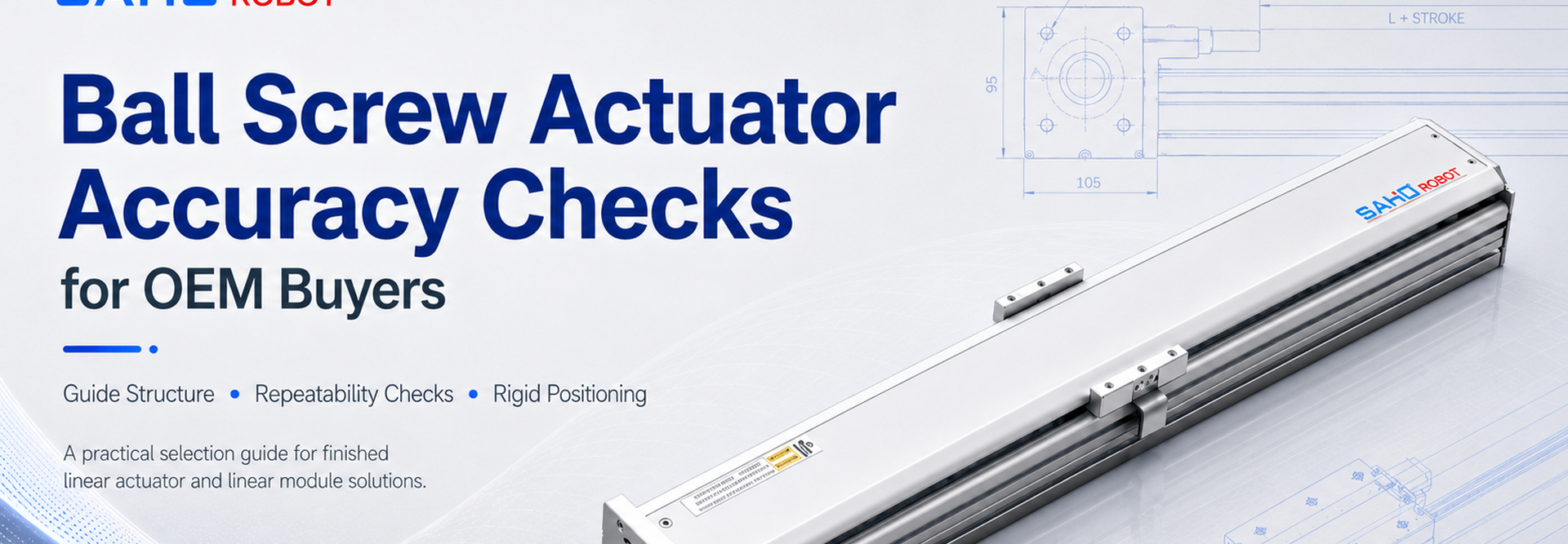
In OEM automation, a ball screw actuator often becomes the mechanical link between design intent and stable production output. However, accuracy does not come from one screw alone. It also depends on load direction, stroke length, carriage support, mounting quality, motor matching, and repeatability checks under real working conditions.
Therefore, this article focuses on practical selection thinking for complete screw-driven linear actuators, linear modules, and motion systems. It does not treat rails, screws, or carriages as separate DIY parts. Instead, it explains how internal structure affects positioning accuracy and when SAHO finished screw drive products become the more reliable choice for OEM equipment, automation integrators, and engineering procurement teams.
Application Scenarios That Create Accuracy Pressure
First, accuracy becomes important when a machine must place, press, inspect, or dispense at the same location many times. In electronic assembly, lithium battery equipment, medical devices, laser processing, and precision inspection, small positioning changes can affect yield. Therefore, motion selection becomes part of process quality, not only mechanical design.
Meanwhile, many production issues do not appear during slow manual jogging. They appear after acceleration, repeated stops, tool contact, or long-cycle operation. As a result, a motion axis that looks acceptable during early testing may show vibration, drift, or inconsistent tool-point position during real production.
In dispensing stations, a nozzle may need to start and stop cleanly near small features. In visual inspection, a camera may need to settle before image capture. In insertion, pressing, or fastening equipment, the tool may push back against the moving carriage. Therefore, the axis must support both motion and process force.
At the same time, OEM machine layouts are often compact. The axis must fit inside guarding, avoid interference with sensors, leave room for cables, and allow maintenance access. For that reason, a complete screw drive module can reduce layout risk compared with a custom axis assembled from many separate components.
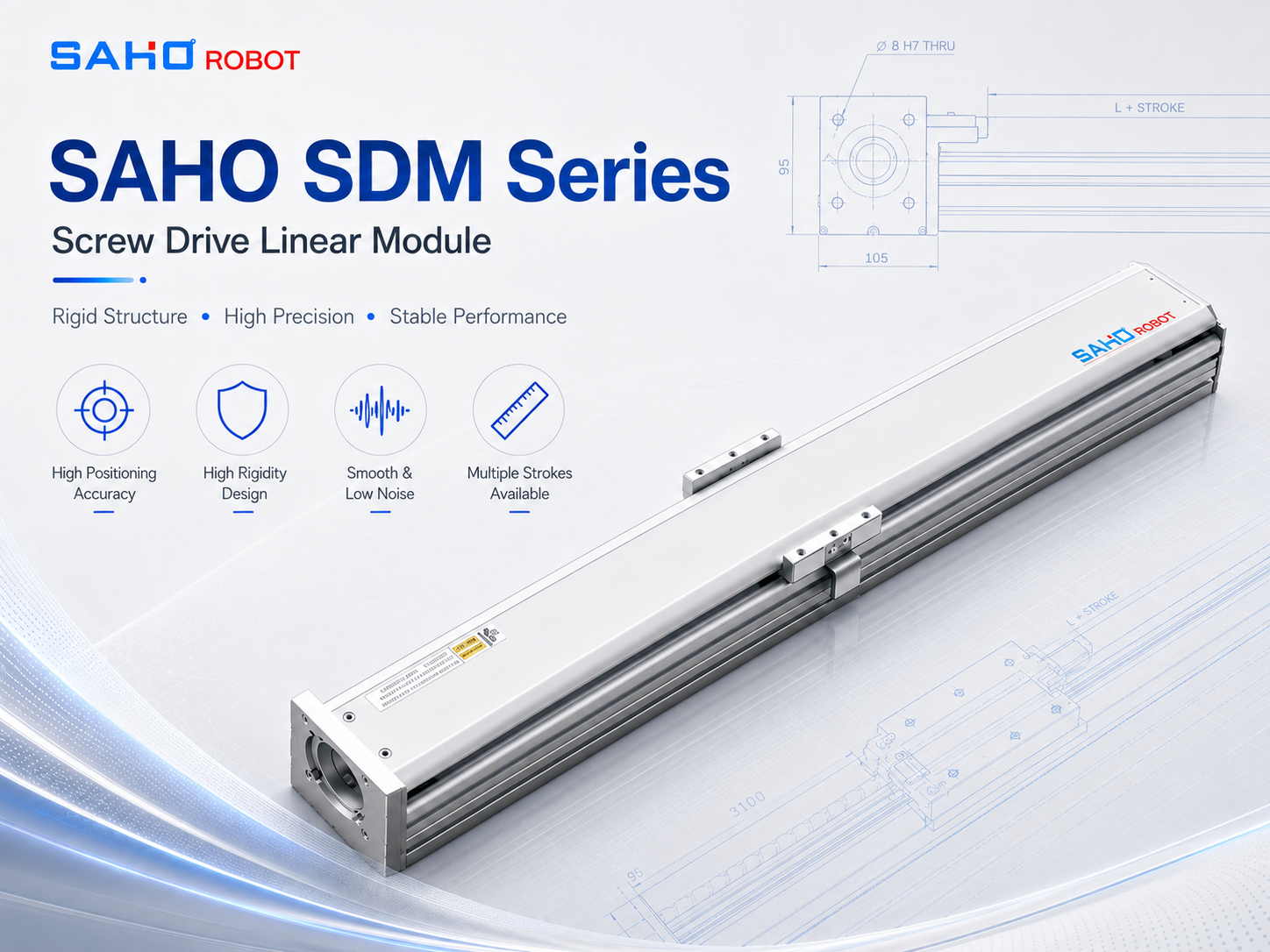
SDM Series covered screw drive module for general automation layouts.
How OEM Teams Should Judge Motion Requirements
Before structure is discussed, the application should be described clearly. The moving object may be a gripper, camera, dispensing valve, pressing head, inspection fixture, or transfer plate. Each load creates different positioning demands, even when the stroke looks similar.
First, payload weight should include all moving items. Tooling plates, brackets, cables, air tubes, fasteners, and sensors all move with the carriage. Therefore, selection based only on product weight can underestimate the real load.
Second, moment load should be reviewed. Moment load appears when the tool sits away from the carriage center. For example, a light nozzle mounted on a tall bracket may create more positioning risk than a heavier but compact fixture.
Third, stroke should include more than working travel. Safe approach distance, homing movement, sensor clearance, and end-of-stroke margin should also be included. However, excessive stroke can increase module size and reduce stiffness.
Finally, speed and acceleration should match the process, not only the cycle-time target. Higher acceleration can shorten travel time, but it may also increase vibration and settling time. Therefore, fast movement and accurate stopping must be considered together.
Why Structure Affects Ball Screw Actuator Accuracy
Ball screw actuator accuracy depends on the complete axis structure. The screw converts rotary motion into linear movement, but the surrounding module controls how stable that movement remains under load. Therefore, the screw, carriage, rail components, bearing support, base profile, and mounting surface must work together.
The screw influences positioning response and drive efficiency. However, a precise screw cannot correct poor support, weak mounting, or a flexible tool plate. As a result, structural stiffness often determines whether catalog performance can appear at the real tool point.
The carriage connects the payload to the moving axis. Its length, mounting surface, and support arrangement affect moment resistance. Therefore, tall tools, offset loads, and pressing forces should be checked before a compact module is selected.
The internal rail components keep the carriage moving along a controlled path. In this article, they are discussed only as internal support parts of a finished actuator or module. They are not the product focus and should not be treated as a separate rail selection tutorial.
Bearing support also matters. The fixed end and support end help control screw rotation and axial movement. As stroke length and speed increase, support quality becomes more important for smooth motion and stable stopping.
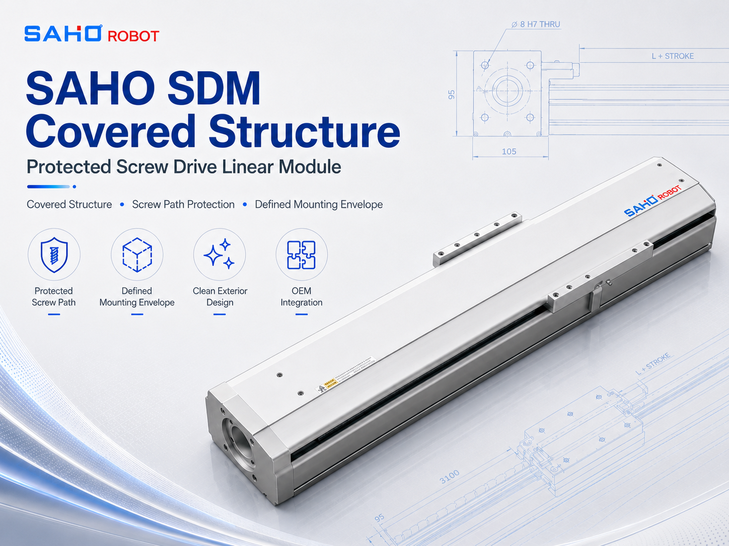
A covered SDM structure helps protect the screw drive path while keeping a defined mounting envelope.
Repeatability Checks for Real Production Conditions
Repeatability checks show whether the axis returns to the same position under repeated motion. This is especially important for assembly, dispensing, inspection, and fixture positioning. A small fixed offset can often be corrected, but unstable repeat behavior usually causes production variation.
First, the test should use the real payload. A bench test without tooling may not show the same deflection, vibration, or settling behavior. Therefore, repeatability should be measured after the axis is mounted on the actual machine frame.
Second, the test point should match the process point. In many machines, the critical location is the nozzle tip, camera center, gripper finger, or press tool. As a result, measuring only near the carriage may hide tool-point error.
Third, repeatability should be checked at production speed and acceleration. Slow movement can make almost any axis look better. However, real production settings may reveal vibration, overshoot, or longer settling time.
In addition, several positions across the stroke should be checked. Cable drag, cover behavior, and support conditions may change across travel. Therefore, one midpoint measurement does not always represent the full working range.
Rigid Positioning in Pressing, Dispensing, and Inspection
Rigid positioning means the moving axis resists unwanted movement when the tool accelerates, stops, or contacts the workpiece. This matters because process quality often depends on the tool point, not only the commanded position.
In dispensing equipment, weak rigidity can cause the nozzle to settle slowly after each move. Therefore, material placement may change near starts, corners, and short segments. A stable axis helps keep bead paths and dot positions more consistent.
In pressing or insertion equipment, force can push the tool backward or sideways. If the carriage, adapter plate, or machine frame flexes, the tool may shift during the critical contact moment. As a result, the process may show inconsistent depth, angle, or placement.
In inspection equipment, vibration can affect image clarity and measurement stability. Therefore, acceleration profile, support structure, cable route, and stop settling should all be reviewed. The goal is not only to arrive quickly, but also to stay stable when measurement begins.
For multi-axis systems, rigidity should be reviewed across the full stack. A lower axis may carry another module, tool head, fixture, and cable chain. Consequently, each added layer increases the need for structural review.
Mounting Direction and Machine Frame Conditions
Mounting direction changes how load enters the actuator or module. Horizontal mounting, vertical mounting, wall mounting, and inverted mounting all create different force paths. Therefore, the same product model may behave differently in different orientations.
Vertical axes need special attention because gravity acts along the direction of motion. Brake motors, mechanical locks, or suitable vertical-axis structures may be required to prevent drop risk. In addition, acceleration and deceleration should be reviewed with gravity in mind.
The machine frame also affects final accuracy. A precise module mounted on a weak or uneven surface may twist under load. As a result, friction, noise, servo load, and repeatability may become worse than expected.
Therefore, mounting preparation should include flatness, stiffness, fastener quality, and alignment. For gantry or X-Y layouts, parallelism and perpendicularity should also be checked. Mechanical setup should not be left for servo tuning to correct later.
Motor, Sensor, and Control Matching
The mechanical module needs a suitable motor and control setup. Servo torque, speed range, inertia match, encoder feedback, and brake requirements influence final behavior. Therefore, motor selection should not become an afterthought after mechanical layout is fixed.
A light tool may respond quickly, while a heavy or offset payload may require more torque margin. In vertical use, gravity and holding requirements add another layer of review. As a result, motor sizing should include acceleration, friction, payload, and safety factors.
Sensors also affect machine behavior. Home sensors, limit sensors, and process position signals should fit the physical stroke and service layout. In addition, cables and air tubes should be routed so they do not pull unevenly on the moving carriage.
Control tuning works best after mechanical checks are complete. A flat mounting surface, correct fastener torque, and aligned load path make tuning easier. Otherwise, software may hide symptoms instead of solving the real structure problem.
Selection Checklist Before Engineering Approval
Before final approval, the motion axis should be reviewed as part of the whole machine. The task, payload, fixture, frame, environment, and control target all influence selection. Therefore, a simple checklist can prevent late-stage redesign.
Define payload weight, including tooling, brackets, fasteners, cables, and moving fixtures.
Check moment load from tool height and distance from the carriage center.
Confirm stroke length with working travel, safe approach, homing movement, and sensor clearance.
Match speed and acceleration with cycle target, vibration control, and settling time.
Review horizontal, vertical, wall, or inverted mounting separately.
Check whether the machine frame provides enough stiffness and flatness.
Plan cable routing so tubes and wires do not pull the moving carriage unevenly.
Run repeatability checks under real payload, real mounting, and production motion settings.
| Check Item | Why It Matters | Practical Selection Thinking |
| Payload | Affects drive force and bearing load. | Include tooling, brackets, cables, and moving fixtures. |
| Moment load | Affects carriage stability and deflection. | Check tool height and distance from the carriage center. |
| Stroke | Influences stiffness, screw behavior, and layout space. | Include working travel, safe approach, and homing distance. |
| Speed | Influences vibration, heat, and settling time. | Review speed together with acceleration and process tolerance. |
| Mounting | Changes gravity load and safety needs. | Review horizontal, vertical, wall, and inverted use separately. |
Where SAHO Screw Drive Products Fit
SAHO provides finished screw drive modules and motion products for automation equipment, not loose rails or single sliding parts. This distinction is important for OEM projects because the motion axis must arrive as a usable mechanical unit with defined structure, mounting logic, and integration path.
For general automation environments, the SDM Series is the main product page for covered screw drive modules. It is the primary landing page for this topic and should be used when the application needs a complete, enclosed screw-driven axis for accurate and rigid positioning.
For layouts that need a European standard screw drive form, the SR Series can be reviewed as a related product path. It should be considered when the machine layout benefits from that open-style integration format.
For broader category comparison, SAHO Robot provides linear motion products across modules, actuators, and motion systems. In addition, SAHO linear motion solutions can support equipment teams that need to compare screw drive, belt drive, and linear motor options within one product ecosystem.
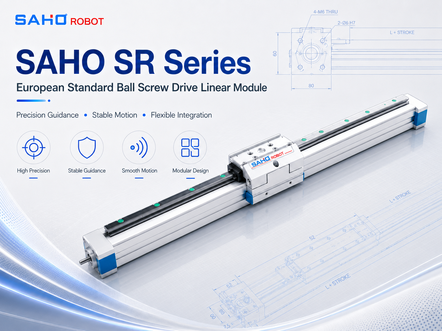
SR Series supports European standard screw drive layouts where open integration and direct mounting are required.
Application Connection: Electronic Component Assembly
Electronic component assembly shows why structure and repeatability matter. Parts are often small, fragile, and sensitive to position changes. Therefore, motion axes used for transfer, pressing, inspection, or dispensing should support stable positioning under real machine conditions.
In this type of equipment, the motion axis may carry a camera, sensor, gripper, nozzle, or fixture. Each tool changes the load path. As a result, module selection should include payload, center of mass, process force, and required settling time.
The Electronic Component Assembly page gives application context for precision production layouts. It helps connect motion product selection with real automation tasks rather than abstract parameter comparison.
Common Selection Mistakes
First, one common mistake is selecting by stroke and payload only. These values matter, but they are not complete. Moment load, acceleration, mounting direction, and process force can change the correct model.
Another mistake is treating repeatability as the only accuracy number. Repeatability confirms return behavior, but it does not show every alignment issue. Therefore, straightness, base flatness, fixture position, and tool-point movement also need attention.
In addition, load offset is often underestimated. A tool mounted far from the carriage center creates twisting force. As a result, the axis may show vibration, uneven wear, or poor stop stability during production cycles.
Meanwhile, some projects rely on servo tuning to solve mechanical problems. Tuning can improve response, but it cannot remove weak mounting, loose brackets, or insufficient support. Therefore, mechanical review should happen before fine tuning.
Finally, maintenance access is sometimes forgotten. Grease points, covers, motor mounts, sensors, and cables need space. Without access, routine service becomes harder and long-term positioning stability may decline.
Maintenance Thinking for Stable Long-Term Motion
First, maintenance protects accuracy over time. Grease condition, contamination, fastener tightness, cover integrity, and cable condition affect motion quality. Therefore, service planning should begin during machine design.
In dusty environments, cleaning and protection become more important. Particles can affect the internal motion path and increase wear. As a result, covers, guarding, and maintenance access should work together.
In high-cycle equipment, lubrication intervals should match actual operating conditions. A station running one shift has different needs from continuous production. Therefore, cycle count, temperature, contamination level, and service windows should guide the maintenance plan.
Finally, maintenance feedback should return to engineering. If several machines show the same wear pattern, the original selection or installation may need review. This feedback loop improves future equipment designs.
Extended Reading
For deeper product comparison and site navigation, the following SAHO pages support the selection path. Each link connects to a relevant product or application area.
FAQ
What should be checked first when evaluating motion accuracy?
First, the real application load should be checked. Payload weight, center of mass, tooling height, cable drag, and process force affect the axis together. Therefore, load data should come before model comparison.
Why do repeatability checks matter in production equipment?
Repeatability checks show whether the axis returns to the same position under real operating conditions. This matters because many stations depend on consistent cycle behavior. As a result, testing should use real payload, speed, acceleration, and mounting.
When does rigid positioning become critical?
Rigid positioning becomes critical when the tool must resist vibration, push force, or off-center loading. Examples include dispensing, pressing, insertion, inspection, and electronic component placement. Therefore, structural stiffness should be reviewed early.
How does stroke length affect selection?
Stroke length affects screw behavior, support needs, module size, and available mounting space. Longer travel can also influence speed limits and settling behavior. Therefore, stroke should include working travel, safety clearance, and homing distance.
Why should a finished module be considered instead of separate parts?
A finished module provides a defined structure, carriage interface, support arrangement, and mounting envelope. Therefore, it can reduce alignment workload, assembly variation, and layout uncertainty in repeat OEM machines.
Which SAHO product page should support this topic?
The SDM Series page is the main landing page for covered screw drive modules in general automation environments. The SR Series page is a related product page for European standard screw drive layouts.
Final Selection Notes
In summary, accuracy depends on the complete motion system. The screw, carriage support, base structure, mounting frame, motor, payload, controller, and test method all work together. Therefore, selection should move from application scene to demand judgment, then to structure review, selection checks, and product matching.
Define payload, moment load, stroke, speed, acceleration, mounting direction, and environment before model selection.
Measure repeatability at the real tool point under the production motion profile.
Use the SDM Series as the main product path when a complete covered screw-driven module is required.
Plan the Next Screw Drive Axis with SAHO
For applications that need a complete ball screw actuator for stable automation positioning, the SDM Series page provides the main product path for covered screw drive modules.







-
-
 English
 -
 Français
 -
 Deutschland
 -
 Italia
 -
 Polska
 -
 España
 -
 Русский язык
 -
 日語
日語 -
 한국
한국 -
 Türkiye
 -
 português
 -
 بالعربيةês
 -
 Tiếng Việt
 -
 คนไทย
คนไทย -
 简体中文
简体中文 -
繁體中文
-