
Date:2026-05-21 Click:120
An industrial ball screw linear actuator is often selected when production equipment needs stable thrust, repeatable travel, and reliable positioning under heavier mechanical loads. In real factory layouts, one axis may carry fixtures, tooling plates, workpieces, inspection heads, press mechanisms, cables, hoses, and sensors. Therefore, the right choice depends on the complete motion task, not only on one payload value.
For heavy-duty automation, SAHO focuses on finished screw driven actuators, linear modules, and motion systems. The actuator body, screw drive, carriage, end support, motor interface, and protection structure work together as one planned industrial automation axis. As a result, equipment teams can reduce alignment risk and keep the machine layout cleaner.
This article follows a practical selection path: application scenario, demand judgment, structure and performance reason, selection checks, and SAHO product fit. It is written for OEM equipment teams, machine builders, automation integrators, factory engineers, and procurement teams that need a reliable heavy load linear actuator for real production equipment.

Application Scenarios Come First
Heavy load motion should begin with the application. A catalog table can show a product family, but the machine decides the real load case. One actuator may move a fixture during transfer. Another may lift a tooling head. Another may hold position while an inspection camera, press head, or welding unit works.
In assembly equipment, the load may look moderate during early design. However, the final moving mass often includes clamps, locating parts, sensor brackets, pneumatic units, cable carriers, air tubes, and adapter plates. Therefore, early selection should include the complete moving assembly, not only the workpiece.
In automotive-related automation, fixtures can become heavier because parts must stay firmly located during positioning, inspection, or assembly. A headlight assembly station, gearbox assembly station, motor controller line, or ignition coil test station may need stable linear motion beside clamps, cameras, rotary units, and servo presses. Consequently, rigidity and repeatable stopping may matter more than maximum speed.
In inspection and measurement stations, the tool may be light, yet vibration can still damage process stability. A camera, probe, laser sensor, or checking head needs a stable position before the next process starts. Therefore, actuator selection should consider motion stability, not only rated force.
In lifting, loading, and transfer systems, the axis may repeat the same movement for many hours per day. The real question is not whether the axis can move the load once. Instead, the question is whether it can move, stop, hold, and repeat under the same production rhythm.
Demand Judgment: When Heavy Load Becomes a Selection Issue
Heavy load does not only mean a high weight number. It also includes load direction, moment load, process force, acceleration, stopping behavior, duty cycle, and mounting stiffness. Therefore, a module that looks acceptable from static payload may still struggle during real production.
A moderate load can become difficult when the center of mass sits far from the carriage center. This offset creates twisting force during acceleration and deceleration. As a result, the axis may show vibration, uneven wear, longer settling time, or reduced positioning consistency.
Process force is another common source of selection error. A station may move a fixture into position and then apply pressing, insertion, sealing, testing, or clamping force. At that moment, the actuator is not only transporting a load. It also supports the force path of the production process.
Duty cycle also changes the meaning of heavy. A 40 kg load moving a few times per hour is very different from the same load moving every few seconds. The second case creates more screw rotation, more bearing load, more heat, and more lubrication demand.
For vertical motion, gravity becomes part of every movement. The axis must lift the moving mass, control downward travel, and prevent uncontrolled drop during stop or power loss. Therefore, vertical use often requires brake planning, safe holding, and careful review of stop behavior.
Total moving mass should include fixture, tool, workpiece, cable carrier, hose, bracket, sensor, and adapter plate weight.
Load center should be checked because offset tooling creates moment load.
Process force should be separated from transport load.
Cycle time should include acceleration, deceleration, dwell time, and settling time.
Installation direction should be confirmed before model selection.
Why an Industrial Ball Screw Linear Actuator Supports Heavy Motion
A ball screw drive converts motor rotation into linear travel through rolling contact. In simple terms, the screw rotates, the nut moves, and the carriage follows the nut along the actuator body. Because rolling contact reduces friction, the axis can deliver controlled thrust with stable motion.
However, the drive mechanism alone is not the full answer. Heavy load motion also depends on the body structure, screw support, carriage design, motor mounting interface, protection design, and machine base. Therefore, a finished screw driven actuator should be reviewed as one complete automation axis.
Compared with a long high-speed transfer axis, a screw driven module is often more suitable when compact stroke, firm stopping, controlled thrust, and repeatable positioning are more important than peak speed. This makes it useful for fixture transfer, inspection positioning, vertical lifting, press support, and adjustment stations.
The screw lead affects motion behavior. A smaller lead can support finer movement and stronger thrust in many layouts. A larger lead can support faster travel when motor torque, screw speed, and stroke length allow. Therefore, lead, motor torque, stroke, acceleration, and load should be reviewed together.
A finished module also reduces integration risk. Instead of aligning a screw, support parts, housing, carriage, coupling, cover, and motor plate separately, the design team starts from a planned motion unit. As a result, the surrounding machine design can focus on tooling, safety, controls, and maintenance access.

Horizontal Load: Inertia, Moment, and Settling Time
Horizontal heavy load motion mainly works against inertia, friction, and process force. During acceleration, a heavy tooling plate may require high torque. During stopping, the same mass may create vibration if the module and machine base lack stiffness.
Therefore, acceleration and deceleration should be reviewed carefully. A machine may use a moderate top speed, yet a short travel distance can still require aggressive acceleration. In that case, the actuator may feel stable during slow testing but become unstable at production rhythm.
Moment load is especially important in horizontal transfer. A wide fixture or offset tool can twist the carriage during movement. This twisting force may not appear in a simple weight calculation. However, it can create uneven wear, noise, position drift, and longer waiting time before the next operation.
Settling time is often the hidden cost. If the axis stops but the fixture still vibrates, the camera, clamp, press head, or inspection tool must wait. This waiting time may become larger than the travel time itself. Therefore, stiffness can improve throughput even when maximum speed does not change.
The machine frame also affects horizontal performance. A rigid module mounted on a weak or uneven base cannot deliver full stability. Therefore, base flatness, bolt pattern, support span, and mounting stiffness should be treated as part of actuator selection.
Vertical Load: Lifting Force, Holding Safety, and Maintenance
Vertical heavy load motion adds gravity to every move. During upward travel, the actuator must lift the full moving mass. During downward travel, the system must control the load and avoid uncontrolled drop. Consequently, vertical applications require more than a normal horizontal sizing check.
A brake motor or mechanical holding method may be needed when the axis must stop in position under load. This is especially important for lifting fixtures, tool heads, press units, and workpiece carriers. Therefore, safe stop behavior should be discussed early, not after commissioning.
Vertical motion also changes lubrication behavior. Gravity can pull lubricant downward, and long strokes may create uneven distribution over time. Therefore, maintenance access, grease interval, and inspection points should be considered in the equipment layout.
In vertical pressing or insertion, the force after reaching position can exceed the moving weight. The actuator may need to hold the tool square to the workpiece while process force travels through the module and machine frame. Therefore, structural rigidity and mounting strength should be reviewed together.

Rigidity, Accuracy, and Repeatability in Production Equipment
Rigidity means the axis resists deflection under load. In factory equipment, rigidity affects tool alignment, fixture stability, noise, service life, and cycle time. A flexible axis may still move, but it may not hold the process point firmly enough during real operation.
Accuracy and repeatability are related, but they are not the same. Accuracy describes how close the axis reaches a commanded position. Repeatability describes how consistently the axis returns to the same position. In many production stations, repeatability has the stronger effect on stable output.
However, accuracy still matters in measuring, camera positioning, laser alignment, dispensing, and test equipment. Over longer strokes, screw lead error, thermal change, mounting distortion, and tooling deflection can affect absolute position. Therefore, the process should define which target matters most.
Rigidity also protects connected equipment. A camera, probe, nozzle, or welding head mounted on an unstable axis may lose process consistency. Meanwhile, a stable linear motion system helps the tool remain square to the workpiece and reduces adjustment time.
Selection Checks Before Choosing a Model
A good selection process should connect application data with mechanical behavior. First, the total moving mass should include every part that moves with the carriage. This prevents undersizing when tooling becomes heavier during detailed design.
Second, stroke should include working travel and extra clearance. Home position, loading position, inspection position, safe clearance, maintenance access, and future adjustment may all need additional travel. Therefore, process distance alone may not be enough.
Third, speed should be described as a motion profile. Top speed does not show acceleration, deceleration, dwell time, or settling time. Consequently, a short move can be more demanding than a longer move at moderate speed.
Fourth, installation direction should be confirmed before model review. Horizontal, vertical, inclined, wall-mounted, and overhead layouts create different load paths. Each orientation changes safety, lubrication, and cable routing requirements.
Moving load: fixture, workpiece, tool, adapter plate, cable carrier, hose, bracket, and sensors.
Load center: distance from the carriage center to the real center of moving mass.
Stroke: loading point, working point, safe clearance, and maintenance space.
Speed profile: acceleration, deceleration, dwell time, and settling time.
Process force: pressing, insertion, sealing, testing, or clamping force.
Environment: dust, oil mist, chips, temperature, humidity, and cleaning method.
Where SAHO Products Fit the Selection Path
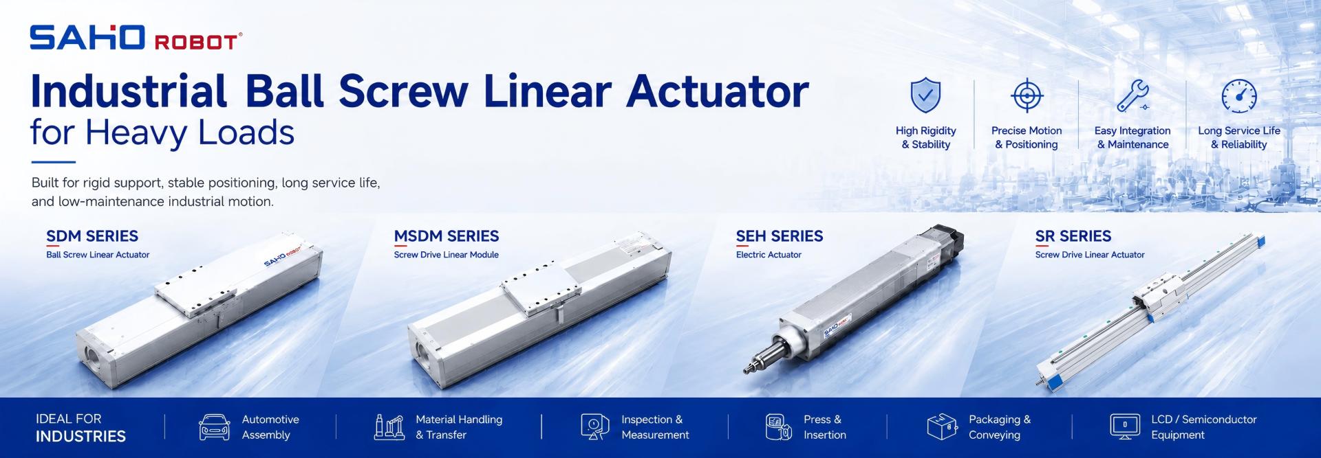
After the application, load direction, rigidity target, and maintenance plan are clear, SAHO product selection becomes more practical. For most heavy-load screw driven automation axes, the industrial ball screw linear actuator path should start from the SDM Series because it is built around finished ball screw linear modules for stable industrial motion.
For compact standardized platforms, the MSDM Series can support clean module integration. For rod-style pushing or lifting layouts, the SEH Series may be reviewed when that actuator form better matches the machine structure.
For related screw drive formats, the SR Series can be used as a comparison path. In automotive automation, the Automotive Industry page also gives useful context for repeatable fixture movement, stable positioning, and long-term production use.

Maintenance, Service Life, and Long-Term Stability
Maintenance planning starts before installation. A screw driven module needs suitable mounting, clean operation, lubrication, and inspection access. Therefore, grease points, cover removal, motor access, and sensor adjustment should not be blocked by fixed machine panels.
Lubrication helps rolling contact remain smooth inside the screw system and support structure. Without proper grease, friction can rise and wear can accelerate. Moreover, contamination can mix with lubricant and create abrasive residue.
In dusty, oily, or chip-heavy production areas, protection matters. Cutting chips, welding debris, abrasive dust, and sticky mist can shorten service life. As a result, shielding, cleaning direction, and machine enclosure design should be considered early.
Temperature also affects reliability. Nearby ovens, welding zones, high ambient heat, or continuous rapid cycling can raise component temperature. Consequently, motor sizing, duty cycle, lubrication method, and thermal expansion should receive attention.
Controller data can support maintenance. Rising motor current, longer settling time, increased following error, or frequent alarms may reveal growing mechanical resistance. In addition, cycle count data can help schedule lubrication before performance drops.
Common Mistakes in Heavy Load Axis Selection
One common mistake is sizing by payload only. Payload matters, but it does not show acceleration, moment load, process force, or installation direction. Therefore, a module that appears suitable under static load may struggle during real cycles.
Another mistake is ignoring the load center. A tool mounted far from the carriage center creates twisting force. Over time, this moment can increase vibration, wear, and positioning error. Therefore, tooling should stay balanced and compact whenever the process allows.
A third mistake is treating vertical and horizontal motion as equal. Vertical motion needs gravity holding and safe downward behavior. Moreover, power loss behavior must be considered before final selection.
Some projects select a drive type too early. Belt drive, screw drive, rack drive, and linear motor structures each solve different problems. Consequently, the process should define load, stroke, speed, accuracy, and environment before the drive family becomes final.
Finally, maintenance access often appears too late. A hidden grease point or blocked motor area increases service time. In addition, a hard-to-clean structure can let contamination build up. Therefore, maintenance layout should appear in the first mechanical review.
FAQ
What makes a screw driven actuator suitable for heavy loads?
A screw driven actuator becomes suitable when the complete structure supports thrust, rigidity, moment load, and repeat positioning. The motor, screw lead, support structure, module body, and mounting frame must match the real load case.
When should a heavy load linear actuator be considered?
It should be considered when a machine needs controlled linear force, stable stopping, compact structure, and repeatable positioning. Typical uses include fixture movement, vertical lifting, press support, inspection positioning, loading equipment, and assembly station transfer.
Can a screw driven module work in vertical motion?
Yes. However, vertical motion requires gravity, braking, holding force, lubrication behavior, and safe stop planning to be reviewed. In many layouts, a brake motor or mechanical holding method should be considered.
Is speed the most important selection factor?
Not always. In heavy load applications, acceleration, deceleration, settling time, rigidity, and process force may matter more than top speed. A smoother move can improve real cycle stability because the next process can start sooner.
What data should be prepared before model selection?
Useful data includes moving load, load center, stroke, installation direction, move time, repeatability target, process force, duty cycle, working environment, motor preference, brake need, cable direction, and available installation space.
Summary
Heavy load linear motion depends on more than payload. The real decision includes mass, load center, moment load, stroke, speed profile, process force, direction, duty cycle, protection, and maintenance. Therefore, a finished screw driven module should be selected as part of the whole machine, not as an isolated mechanical item.
SAHO SDM Series screw drive modules provide a practical product path for rigid positioning, compact thrust, vertical lift planning, fixture movement, and repeatable industrial automation motion. The strongest result comes when the actuator, machine frame, tooling, motor, controls, and maintenance access support the same process goal.
First, define the full moving mass, load center, stroke, installation direction, process force, and cycle rhythm.
Next, review rigidity, braking, mounting flatness, cable route, environment, and lubrication access as one system.
Finally, compare the axis requirement with SAHO SDM Series or related screw drive modules before final layout approval.
For heavy-duty positioning, lifting, fixture movement, and assembly equipment, the correct industrial ball screw linear actuator can improve motion stability and reduce integration risk.


-
-
 English
 -
 Français
 -
 Deutschland
 -
 Italia
 -
 Polska
 -
 España
 -
 Русский язык
 -
 日語
日語 -
 한국
한국 -
 Türkiye
 -
 português
 -
 بالعربيةês
 -
 Tiếng Việt
 -
 คนไทย
คนไทย -
 简体中文
简体中文 -
繁體中文
-