
Date:2026-05-18 Click:68
In precision assembly, small position errors rarely stay small. Therefore, a stable ball screw linear module must support repeatable stopping, rigid fixture movement, clean guide support, and predictable process timing from the first trial run to long-term production.
The Real Pain Point: Small Assembly Errors Keep Coming Back
First, precision assembly problems often look smaller than they really are. A connector may sit slightly off-center. A screw may enter at a small angle. A dispensing line may become uneven near the edge. At the beginning, these defects may look random.
However, repeated errors usually point to a motion stability issue. The station may reach the programmed position, yet the fixture may still shake, tilt, or settle slowly. As a result, the tool starts working before the product is truly stable.
In real production, this creates more than one defective part. It creates extra inspection work, unstable yield records, more trial adjustments, and longer communication between mechanical design, electrical control, production, and procurement teams.
Therefore, the motion axis should not be selected only by travel distance. It must support the fixture, the load center, the tool force, the stopping accuracy, and the real rhythm of the assembly line.
Why Motion Drift Happens in Precision Assembly
In many stations, the problem does not come from one part alone. Instead, it comes from the whole force path. The carriage supports the fixture. The fixture supports the product. Then, a nozzle, screwdriver, press head, gripper, camera, or probe interacts with the product.
If the fixture plate is wide, the load center can move far away from the carriage center. This creates moment load, which means twisting force. Even a light part can become difficult to control when the fixture is offset or the tooling force enters from one side.
Meanwhile, cable chains, air tubes, sensor brackets, and protective covers can add hidden drag. These parts may look minor in a drawing, but they can pull against the carriage during acceleration or near the end of travel.
For this reason, a station that looks stable during a slow dry run may become unstable at real production speed. The cause is not always poor programming. Often, the mechanical structure does not give the servo system enough stable support.
How Screw-Drive Motion Supports Precision Assembly
First, check whether the process needs firm stopping rather than only fast movement. Screw drive is often suitable when the station performs fine alignment, part positioning, inspection feeding, screw fastening, adhesive dispensing, light press-fit, or contact testing.
Next, observe what happens after the axis stops. If the fixture still vibrates, the next process may need extra waiting time. In that case, maximum speed does not help much. Stable stopping can matter more than peak travel speed.
In addition, review whether the module needs to resist force after stopping. When a tool touches the product, the carriage and guide structure must hold position. This is where screw-drive rigidity can improve process consistency.
Finally, compare the motion requirement with the assembly window. If the station needs repeatable position, compact structure, controlled acceleration, and good fixture support, a screw-driven module is usually a practical starting point.

Key Checks: Load, Stroke, Speed, Accuracy and Installation Direction
Load and Load CenterFirst, include the fixture, product, clamps, sensors, cable brackets, and adapter plates. More importantly, note the distance from the load center to the carriage center because offset load can create twisting force. | Stroke and Working PointsNext, define loading, inspection, assembly, reject, safe clearance, and maintenance positions. A longer stroke is not always better because compact equipment needs enough travel without wasting space. |
Speed and Settling TimeMoreover, real output depends on acceleration, deceleration, and vibration after stopping. A smoother move can sometimes shorten the full cycle because the next action can start sooner. | Installation DirectionFinally, horizontal, vertical, side-mounted, and inverted layouts create different risks. Vertical use may require brake planning or mechanical locking to prevent gravity drop. |
Accuracy should also be checked under real working conditions. A no-load repeatability test may look good. However, pressing force, screw torque, cable drag, fixture offset, and frame vibration can change the final process result.
At the same time, the base plate should be flat and rigid. A strong module can still lose accuracy if mounted on a thin, twisted, or vibrating frame. For precision assembly, mounting quality is part of the accuracy system.
Therefore, the best judgment method is simple. Test the module with the real fixture, real load, real speed, real tooling action, and real inspection standard. This gives a more honest picture than catalog data alone.

Fixture, Guide Rail and Tooling Plate Matching
First, the fixture should sit close to the carriage support area. This reduces twisting and helps the guide structure hold the product in a stable position. When a fixture plate becomes wider, moment load usually increases faster than expected.
Meanwhile, locating pins and clamps should not fight the motion direction. A product should settle naturally into the nest. Otherwise, the module may stop correctly while the part sits slightly biased inside the fixture.
In addition, tooling force must travel through a strong path. A press head, screwdriver, probe, or nozzle creates reaction force. If the tooling plate bends, the process point can move even when the carriage position is correct.
Therefore, fixture drawings should be shared before module selection is finalized. A simple sketch showing plate size, load center, clamp location, and tool force direction can prevent late-stage redesign.
Environment, Cleanliness, Maintenance and Motor Compatibility
First, the working environment can change module performance. A clean electronic assembly area may require better dust control. A general workshop may face particles, oil mist, adhesive residue, or fine debris. As a result, cover design and cleaning routine should be discussed early.
Meanwhile, maintenance access should not be hidden behind brackets or machine covers. Grease points, guide surfaces, cable chains, and screw areas need enough space for inspection. Better access helps maintain repeatability over long operation.
Motor compatibility also matters. Many automation lines already standardize servo brands for spare parts and commissioning. Therefore, motor flange, brake option, cable direction, encoder requirement, and controller platform should be confirmed before final selection.
In addition, delivery communication should include whether the project uses a standard stroke or a custom stroke. Standard models may move faster. Customized options need clearer drawings, mounting requirements, and technical confirmation.
For procurement planning, this information reduces uncertainty. It also helps compare the quotation on the same technical basis instead of comparing only model names or outer dimensions.
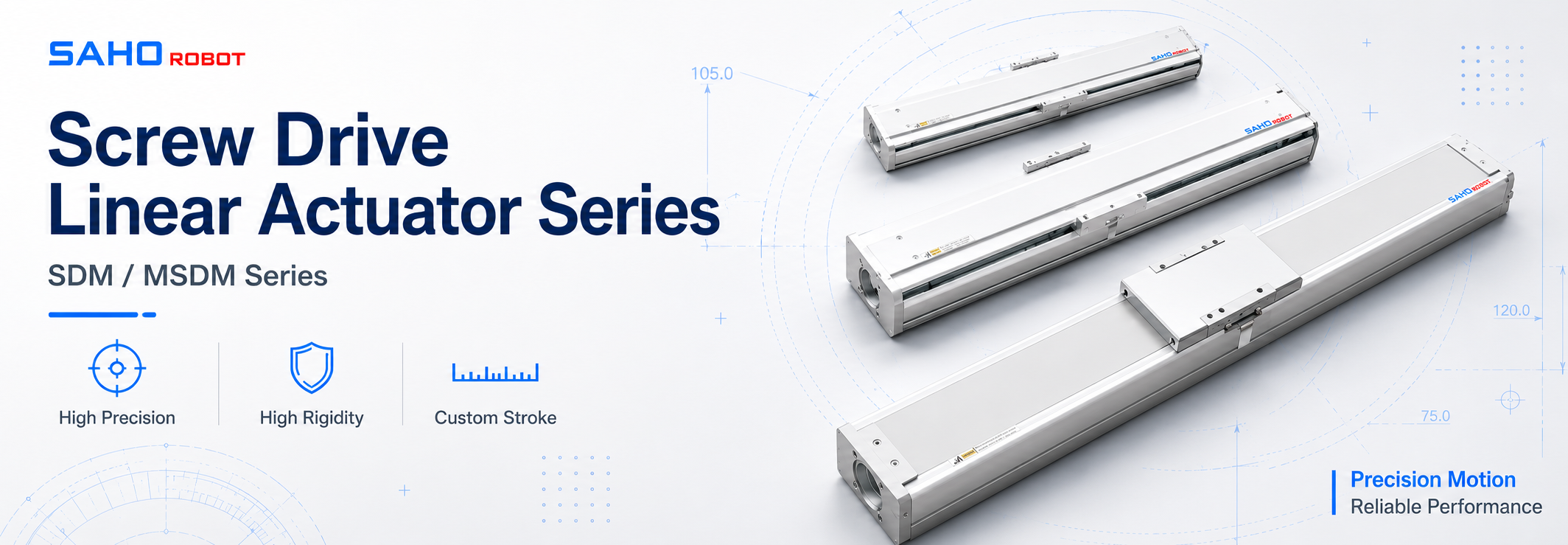
Naturally Matching the Station to SAHO SDM and MSDM Series
After the pain point, cause, and judgment method are clear, product selection becomes more practical. For many precision assembly stations, SDM Series can serve as the main screw-drive positioning axis. It fits guided fixture travel, inspection feeding, small part positioning, and controlled process movement.
Meanwhile, the MSDM Series can support compact or standardized machine platforms. It is useful when equipment layout needs a cleaner module format, a compact structure, and consistent mounting across repeated station designs.
However, model choice should still come from the real process. Load, stroke, speed, accuracy, installation direction, environment, motor preference, and fixture structure all affect the final recommendation.
For broader system planning, SAHO linear motion solutions can connect screw-drive modules with multi-axis automation needs, machine frames, tooling layouts, and long-term production support.

Application Fit: Precision Assembly and Electronic Component Handling
In electronic component assembly, parts are often small, but the process window can be narrow. A module may move a carrier under a camera, place a product below a dispensing nozzle, present a connector for insertion, or shift a tray into a testing point.
Therefore, the motion system must support more than simple transfer. It must keep the part stable before inspection, keep the fixture steady during contact, and allow the next action to start without unnecessary waiting time.
The Electronic Component Assembly application direction is useful for this type of planning because it connects precision motion with real manufacturing rhythm, process stability, and automation output.
Inquiry Data Engineers and Procurement Teams Should Prepare
Before model confirmation, a clear inquiry package can reduce back-and-forth communication. It also helps engineering and procurement teams discuss the same technical basis.
Moving load: fixture weight, product weight, clamp weight, adapter plate weight, and cable bracket weight.
Load center: distance from the carriage center to the real center of the moving mass.
Stroke: total travel, loading position, inspection position, assembly position, reject position, and safe clearance.
Speed: target cycle time, acceleration expectation, allowed settling time, and production rhythm.
Accuracy: repeatability target, tooling tolerance, vision correction method, and final inspection standard.
Installation direction: horizontal, vertical, side-mounted, inverted, or multi-axis combination.
Environment: dust level, cleanroom requirement, adhesive exposure, oil mist, temperature, humidity, and cleaning method.
Maintenance: lubrication access, guideway cleaning access, expected service interval, and replacement space.
Motor compatibility: servo brand, motor flange, brake requirement, cable exit direction, encoder type, and control platform.
Delivery communication: standard model need, custom stroke need, drawing confirmation, quantity plan, and expected project schedule.
With these details, technical review becomes more accurate. As a result, the selected module can match the real station instead of only matching a rough travel distance or a model name.
Extended Reading
For deeper selection planning, the following pages help connect product choice with real automation applications.
Screw-drive actuator series for general precision motion and assembly positioning. | Compact screw-drive module option for standardized machine platforms. | Application reference for precision automation and electronic assembly planning. |
FAQ
Q1. What makes a ball screw linear module suitable for precision assembly?
A ball screw linear module is suitable when the station needs repeatable positioning, firm stopping, and stable fixture support. It is often used for inspection feeding, dispensing, fastening, light press-fit, and contact testing.
Q2. Which data should be prepared before selecting a module?
First, prepare moving load, stroke, speed, repeatability target, installation direction, fixture size, and load center. In addition, motor preference, cable direction, dust level, maintenance access, and delivery expectations should be included.
Q3. Is speed the most important selection factor?
Not always. In precision assembly, settling time after stopping can matter more than maximum speed. A controlled move with less vibration can improve real cycle stability.
Q4. Can the module be installed vertically?
Yes, vertical installation can be considered. However, gravity changes the risk. A brake motor, mechanical lock, or safety method may be needed depending on load, stroke, and stop position.
Q5. When should MSDM Series be considered?
MSDM Series can be considered when the equipment needs a compact screw-drive module, standardized structure, and clean mounting layout. However, final selection should still depend on load, stroke, speed, accuracy, and installation direction.
Precision Assembly Module Selection
Prepare the Motion Data Before Model Confirmation
In short, stable assembly starts with clear data. Load, stroke, speed, accuracy, installation direction, fixture shape, motor preference, and environment details help SAHO match the motion axis to the real station.
For model discussion, prepare the full process picture rather than only a stroke value. This makes selection cleaner, quotation communication faster, and later commissioning more predictable.
First, prepare moving load, load center, fixture size, and process force direction.
Next, confirm stroke, speed, cycle time, repeatability target, and mounting direction.
Finally, share drawings, motor preference, cable direction, dust or cleanliness needs, maintenance access limits, and expected delivery schedule.


-
-
 English
 -
 Français
 -
 Deutschland
 -
 Italia
 -
 Polska
 -
 España
 -
 Русский язык
 -
 日語
日語 -
 한국
한국 -
 Türkiye
 -
 português
 -
 بالعربيةês
 -
 Tiếng Việt
 -
 คนไทย
คนไทย -
 简体中文
简体中文 -
繁體中文
-