

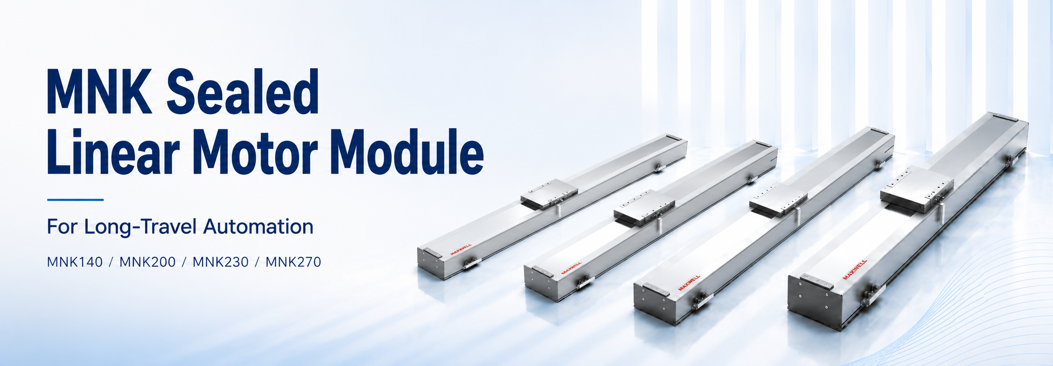
A camera head may cross a machine in less than a second and still leave the process waiting for the image to settle. A dispensing axis may meet its speed target but lose consistency as the hose changes direction. In both cases, the motor is only part of the decision. SAHO’s sealed linear motor module in the MNK Series brings the motor, guidance, feedback, moving table, and protective structure into one axis package. The useful question is whether that package fits the move your machine actually has to make.
MNK140, MNK200, MNK230, and MNK270 offer different widths and force ranges for that choice. A compact inspection head may need little thrust but careful control of its overhang; a long transfer platform may need more continuous force than its workpiece weight suggests. Looking at these differences before selecting a model helps avoid paying for unused capacity—or discovering a mechanical limit after the frame has been built.
Start with the move: describe what travels, what happens when it arrives, and what the axis is exposed to. Those three answers are more useful than choosing the largest force value in the table.
What the Integrated Module Changes for the Machine Builder
An MNK axis produces thrust directly along the travel direction, without a screw or timing belt converting rotary motion. The motor, guided moving platform, feedback, and protective construction form a coordinated module. For a machine builder, the practical benefit is having fewer separate guide, encoder, cover, and carriage interfaces to design and align.
That benefit becomes easier to see on a long machine. A separately built axis needs room for the magnetic track, guideway, scale, cable route, covers, and end functions, with their alignment maintained over the full stroke. An integrated module can simplify that work when its standard envelope fits. It still needs a suitable supporting frame, controller, external cables, process tooling, and machine guarding.
The motor supplies thrust; the guide carries the load. A camera on a tall bracket can be easy to accelerate yet difficult to hold steady. Its center of gravity and pitch, yaw, or roll moments may decide the module size before motor force does. When space is tight, lowering the bracket or bringing the tool closer to the carriage can be worth evaluating before moving to a wider series.
Feedback selection follows the same logic. MNK designation information identifies magnetic and optical grating options, along with incremental and absolute choices. The right configuration depends on the measurement task and controller interface. A finer resolution alone cannot correct a flexible support, temperature drift, or an installation error.
MNK140, MNK200, MNK230, and MNK270 Model Comparison
The MNK family uses four base-width groups: MNK140, MNK200, MNK230, and MNK270. Each group covers several continuous and peak thrust configurations. Their force ranges overlap: a wider series does not necessarily provide more thrust than every configuration in a narrower series. Compare the selected motor option, not just the number in the family name.
The published MNK series specifications list travel from 100 mm to 5,500 mm and maximum speed up to 5 m/s. These are configuration limits, not a promise that every payload can achieve the longest travel and highest speed together. The MNK140 technical data label maximum speed as a no-load value; confirm the speed condition for the exact model and its loaded motion profile.
| Series | Continuous thrust range | Peak thrust range |
|---|---|---|
| MNK140 | 103–308 N | 289–868 N |
| MNK200 | 181–725 N | 512–2,048 N |
| MNK230 | 292–1,166 N | 823–3,292 N |
| MNK270 | 400–1,600 N | 880–3,520 N |
Continuous thrust represents force that can be sustained under the specified thermal conditions. Peak thrust supports short acceleration or disturbance events, but it cannot replace continuous-force sizing. A design that only fits the peak column may overheat during repeated cycles. The full cycle must be checked against both force limits.
| Series | Published travel range | Published maximum speed* |
|---|---|---|
| MNK140 / 200 / 230 / 270 | 100–5,500 mm | Up to 5 m/s |
*Speed condition: the MNK140 technical data identify maximum speed as a no-load value. Confirm the specified conditions for the exact model; loaded speed depends on force at speed, drive voltage and current, moving mass, stroke, cables, and duty cycle.
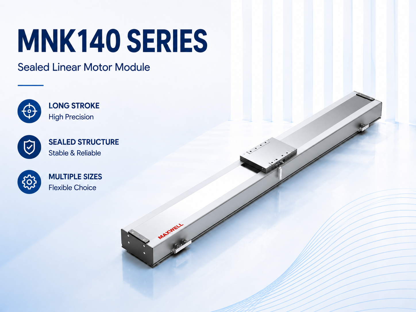
MNK140 for lower-force, narrower layouts
MNK140 is the narrowest group in this comparison. Its 103–308 N continuous and 289–868 N peak ranges make it worth screening for compact inspection heads, cameras, and small dispensing tools. These are application starting points, not payload ratings: a light head on a tall bracket can still create demanding guide moments.
MNK140 is especially worth examining when neighboring stations leave little room across the axis. Before accepting the narrow envelope, sketch the complete tooling plate and its service access on the drawing. If the bracket must reach far beyond the carriage to do the job, that apparent space saving may create a stiffness problem.
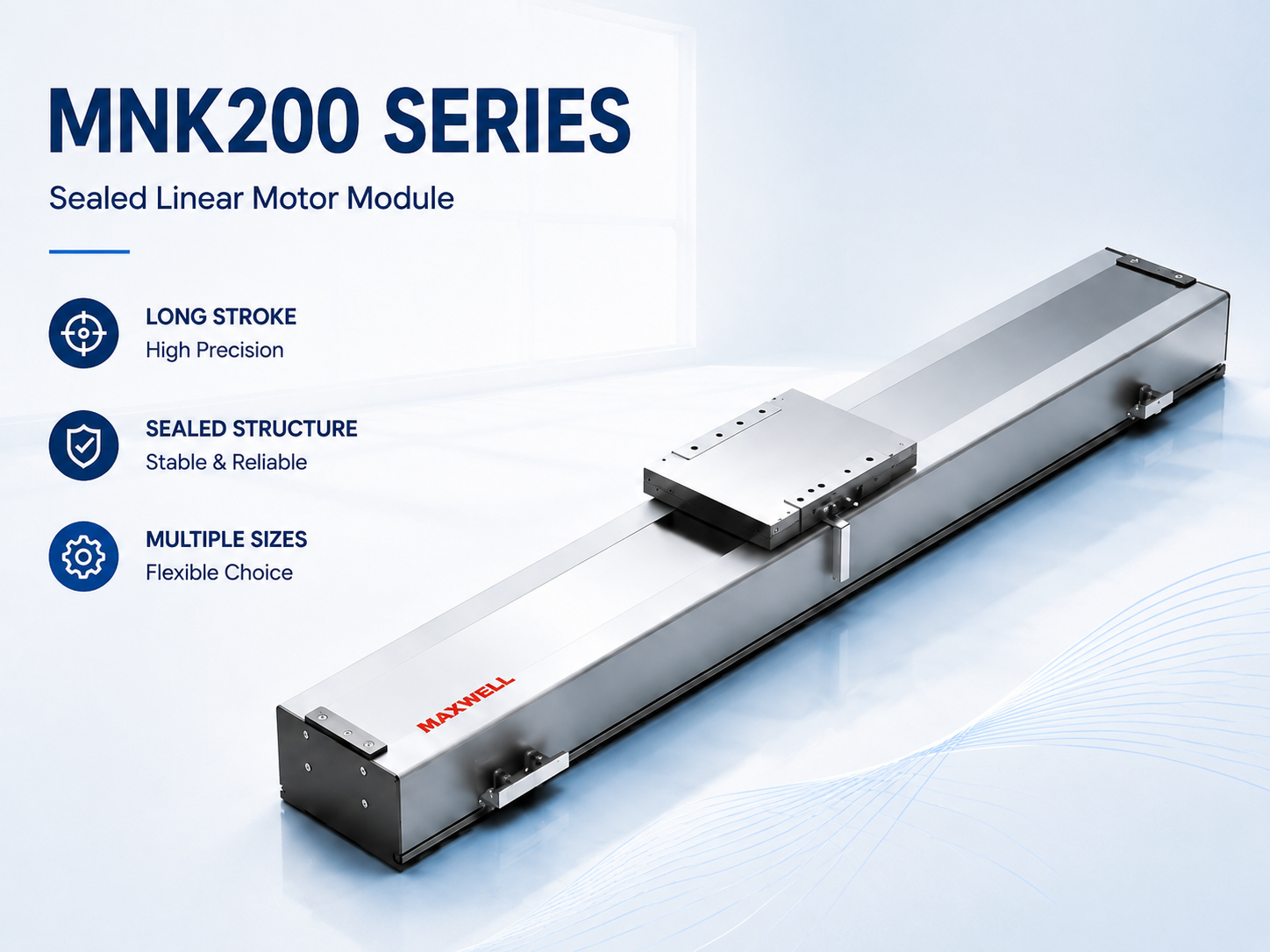
MNK200 for higher thrust requirements
MNK200 extends the available force range to 181–725 N continuous and 512–2,048 N peak. Evaluate its configurations when MNK140 leaves insufficient continuous-force or acceleration margin. Because the ranges overlap, a high-output MNK140 and a lower-output MNK200 may both deserve review; mounting width, guide loading, cooling, and the actual force pair decide between them.
The decision is not simply “more payload means MNK200.” If a smaller module already passes the force and guide checks, moving up may add width without improving the process. MNK200 becomes more compelling when the actual cycle needs its available continuous force or the selected mechanical arrangement fits the tooling better.
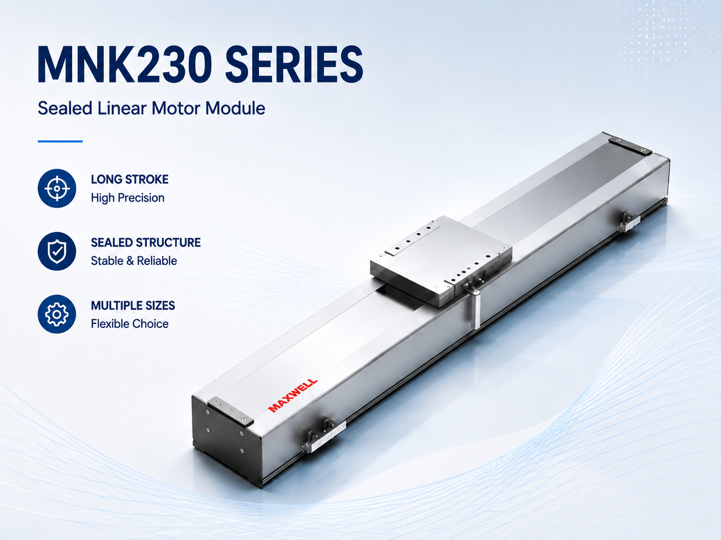
MNK230 for higher continuous and peak force
MNK230 offers 292–1,166 N continuous thrust and 823–3,292 N peak thrust across its configurations. It deserves evaluation for larger moving structures, faster ramps, or stronger process reactions. The upper end provides more force than MNK200, but each candidate must still pass the full-cycle thermal check and the guide-load review.
For a machine that repeats the same move all shift, the continuous rating can matter more than an impressive peak value. A brief acceleration burst and a sustained process load place different demands on MNK230. Compare the cycle as a whole, including any force applied while the carriage appears to be stationary.
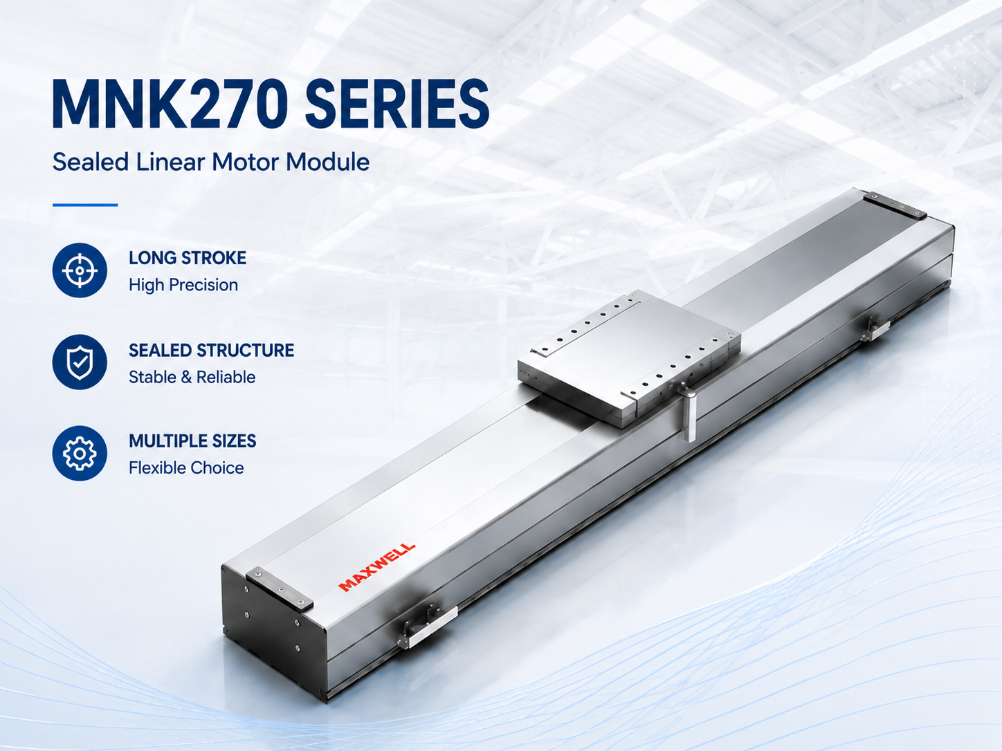
MNK270 for the highest published MNK force range
MNK270 has the highest published upper limits among these four groups: 1,600 N continuous and 3,520 N peak, within ranges starting at 400 N and 880 N respectively. Those upper limits can help with demanding sustained loads. They do not establish a permissible payload or make every MNK270 configuration stronger than every MNK230 configuration.
MNK270 should earn its place through the load and cycle requirements. A wider module also needs room for installation, lifting, cable routing, and later service. On a stacked system, the mass carried by the lower axis changes with the upper-axis choice, so check the complete layout before treating a larger model as extra insurance.
Why the Fastest Axis May Not Give the Shortest Cycle
Maximum speed is easy to compare in a catalog. Production timing is less simple: the axis has to accelerate, travel, brake, settle, complete its task, and often return. On a short move, it may never reach the speed being specified. On a long move, cable behavior and the time spent under load become more significant. Start with the required cycle and work back to the motion profile.
The basic acceleration force is moving mass multiplied by acceleration. Include the module's moving carriage or mover assembly, tooling plate, brackets, workpiece, the moving share of cables, and any carried axis. Check what the supplier already includes so that the carriage is neither omitted nor counted twice. Process resistance, friction, and cable drag add signed forces; vertical or inclined motion also includes the gravity component along the axis.
Basic force check: required drive force includes acceleration force, process force, friction or drag, gravity where applicable, and a justified engineering margin. The acceleration term is calculated from total moving mass × target acceleration.
Peak force governs the hardest short event, often during acceleration or deceleration. For preliminary thermal sizing, calculate the root-mean-square force over the repeating cycle: FRMS = √[Σ(Fi² × ti) / T], where T includes moves, holds, and idle periods. Compare it with the selected configuration's continuous rating under the applicable cooling and ambient conditions. Peak duration, drive current and voltage, and the force available at speed also need confirmation; RMS alone is not final motor approval.
That RMS method prevents a common mistake: averaging positive and negative forces directly. Acceleration and braking may cancel in a simple arithmetic average, while both still create motor heating. Because the squared terms stay positive, RMS force captures their thermal contribution. Process dwell with sustained force must also remain in the calculation.
Travel length and cycle time should be checked together through a motion profile. The profile needs acceleration distance, constant-speed distance, deceleration distance, settling time, process dwell, and return motion. If the requested speed cannot be reached within the available stroke, that speed adds little value. A lower maximum speed with optimized ramps may deliver the same throughput.
Likewise, a published maximum of 5 m/s does not mean every configuration should run at that value. Payload, encoder behavior, structural resonance, cable carrier limits, control bandwidth, and stopping distance may set lower practical limits. Long-travel emergency stopping is especially important because stored kinetic energy rises with mass and speed. Mechanical end protection cannot replace controlled limit logic.
Duty cycle also affects cooling decisions. A fast move followed by a long idle period differs from continuous scanning, even when peak force matches. A process that holds force during dwell can create substantial heat without visible motion. Supplying a complete timing chart makes thermal assessment more reliable than a single cycles-per-minute value.
Installation direction adds another layer. Horizontal travel mainly demands dynamic force and resistance compensation. Vertical travel requires continuous support against gravity, plus a safe holding strategy during power loss. Angled motion divides gravity along the travel direction. The same payload may need different motor capacity across horizontal, vertical, and inclined layouts.
Worked example: screening a horizontal inspection axis
Consider a hypothetical 1.0 m indexing move with 40 kg total moving mass, including the moving carriage and tooling. Assume 5 m/s² acceleration and deceleration, a target speed of 2 m/s, and 40 N constant resistance opposing motion. Each end has a 0.5 s inspection dwell with no applied holding force. The return move is identical. This simplified example excludes jerk-limited ramps and models each dwell at zero motor force; a real cycle must use measured or calculated holding demand.
Reaching 2 m/s takes 0.4 s and 0.4 m. Braking takes another 0.4 s and 0.4 m, leaving 0.2 m at constant speed for 0.1 s. One move therefore takes 0.9 s, and the out-and-back cycle with two dwells takes 2.8 s.
Acceleration: 40 × 5 + 40 = 240 N for 0.4 s.
Constant speed: 40 N for 0.1 s.
Deceleration: 40 × (−5) + 40 = −160 N for 0.4 s. Resistance assists braking.
Full-cycle RMS: √{2 × [(240² × 0.4) + (40² × 0.1) + (160² × 0.4)] / 2.8} ≈ 155 N.
The preliminary demand is 240 N peak and approximately 155 N RMS before allowances. An MNK140 option rated at 103 N continuous fails the thermal screen even though its 289 N peak rating exceeds the acceleration demand. A higher continuous-force MNK140 configuration may remain a candidate; MNK200 may also warrant review. Neither is approved by this calculation alone: verify the paired ratings, force at 2 m/s, peak duration, moving mass, guide moments, drive limits, and cooling for the actual configuration.
The same motion profile also shows why the 5 m/s headline is not the selection target. At 5 m/s², reaching and then leaving 5 m/s needs 5 m of travel before any constant-speed segment. It cannot fit this 1 m move. Improving settling or reducing moving mass may contribute more to throughput than specifying a higher maximum speed.
Where the Enclosure Helps—and What Still Needs Checking
An enclosure can be valuable on an axis running beside a dusty handling process. It does not follow that the same configuration is suitable beside coolant spray or a washdown area. The direction of exposure matters: falling particles, airborne mist, and pressurized liquid can reach different openings. Describing the actual process is more useful than asking whether the module is simply “sealed.”
MNK is presented as an enclosed stage, but the family description is not an automatic waterproof or IP-rating claim. Its designation information includes steel-band and sealed-type codes. Compare the cover, carriage openings, and cable entries on the drawing for the proposed configuration, and obtain written confirmation against the required environment.
A useful first step is to mark where contamination originates on the machine sketch. If a small process shield can redirect chips or droplets before they reach the axis, it may be a better solution than expecting the cover to handle direct exposure. Leave enough access to inspect and clean the carriage area without dismantling neighboring stations.
Cleaning deserves its own sentence in the inquiry. A module exposed only to dry dust during production may face solvents, spray, or high-pressure air during maintenance. Identify those conditions, along with condensation, ambient temperature, and nearby heat sources. High temperatures reduce thermal margin; cold conditions can change grease behavior and cable flexibility.
Before ordering: ask whether the quoted protection and cleaning conditions apply to the exact cover and cable-entry arrangement being supplied. If the answer depends on extra shielding, include that shielding in the machine layout and cost.
The Installation Details That Change the Result
A long axis can look straightforward in a layout until the moving services are added. The camera needs a signal cable, the tooling needs power, and a dispenser may bring a hose whose resistance changes during the move. All of that travels with, or acts on, the carriage. Reviewing the real cable package early can prevent a late change to both the drive sizing and the frame.
Allow room for the carrier’s bend radius, return path, attachment points, and service access. Use the carrier manufacturer’s guidance for fill, separators, unsupported or gliding travel, speed, and acceleration. Clamp fixed and moving cable ends outside the bending zone so repeated motion does not pull on the connectors. The attachment should not twist the carriage as the carrier reverses.
A good bench result still needs to work in the machine
Tall tooling, a long support beam, or an upper axis can introduce vibration that was absent during an unloaded test. A representative payload and the actual cable arrangement should therefore be part of tuning and full-stroke checks. If the process is stop-and-capture inspection, measure when the image can be taken reliably, rather than accepting travel time alone.
Confirm the feedback interface, Hall-sensor requirements, commutation method, drive current and voltage, and homing behavior with the proposed motor configuration. Route and shield feedback wiring according to the equipment guidance, keeping it separated from motor power where required. Direction and polarity checks belong in the manufacturer’s controlled commissioning procedure before normal operation.
Home sensing, software limits, hardware limits, and mechanical stops perform different jobs. Their locations must allow for the real stopping distance and fault response, with access to adjust or replace sensors. Neither a compact drawing nor a nominal stroke figure is a reason to remove that space.
When one MNK axis carries another
In a stacked XY arrangement, the lower axis moves the complete upper module as well as the tooling and workpiece. Include brackets and the carried cable package, and compare guide moments as well as acceleration force. A gantry adds a different demand: the two sides need suitable synchronization and fault handling to control racking.
Vertical motion also requires sustained support against gravity. Check the holding force against thermal limits and agree a power-loss strategy such as an appropriately designed brake, counterbalance, or locking arrangement. Motor thrust alone should not be the only protection against a falling load. These arrangements need to be designed into the machine before the axis order is finalized.
MNK vs NK and Bare Linear Motors
MNK, NK, and bare linear motors can all create direct linear motion, yet they solve different integration problems. MNK emphasizes an enclosed, complete module platform. The linear motor stage in the NK Series uses a steel-belt protected structure. Bare motors supply the electromagnetic drive components while leaving more mechanical architecture to the machine designer.
MNK is worth prioritizing when the standard module fits the machine and a coordinated axis saves meaningful design and assembly work. A custom guide and carriage may offer more freedom, but that freedom is useful only if the project needs it. Compare the work required to reach a reliable production axis, not just the purchase price of the electromagnetic components.
NK is marketed around steel-belt protection, while MNK is presented as an enclosed stage. Treat this as a starting point for comparing the actual drawings. Check cover codes, carriage openings, cable outlets, service access, and the specified exposure conditions; do not assume one series always provides stronger environmental protection.
A bare motor creates the most freedom around guide selection, encoder placement, carriage shape, and machine structure. That freedom benefits specialized platforms with unique geometry or extreme packaging constraints. At the same time, the design team must engineer alignment, air gap, track installation, guide accuracy, covers, cable routing, sensors, and thermal behavior. Integration effort can exceed the apparent simplicity of the component purchase.
The compact iron core linear motor from the WJM Series represents that component-level direction. Its compact iron-core format supports force density in custom direct-drive structures. Yet WJM does not replace the need for a guide, encoder, base, carriage, cover, and cable system. It fits projects prepared to own those mechanical decisions.
| Selection direction | Best fit | Main engineering responsibility |
|---|---|---|
| MNK | Enclosed, integrated long-travel platform | Payload, frame, environment, cables, controls, and safety integration |
| NK | Steel-belt protected integrated stage | Protective layout, environment, frame, cables, controls, and safety |
| Bare motor | Custom geometry and component-level architecture | Complete guide, feedback, alignment, structure, protection, and commissioning design |
Total project effort provides a better comparison than component price alone. Design hours, machining, alignment, covers, encoder installation, cable hardware, tuning, documentation, and service access all have value. The most economical solution may be the one that reduces integration uncertainty. That answer can differ across production volume and machine architecture.
Match the Axis to What Happens at the Tool
Two machines in the same industry can need very different axes. A panel transfer has to arrive without disturbing the workpiece; a dispensing head has to maintain its path while the hose moves; an inspection head may spend more time settling than traveling. These process differences help decide which MNK configurations deserve a closer look.
Electronic assembly and inspection lines
In electronic component assembly automation, long axes may move cameras, placement heads, dispensers, fixtures, or test tooling. Direct drive response can support repeated indexing without belt stretch or screw transmission. The enclosed module format helps create an orderly equipment layout around small parts and dense tooling.
For stop-and-capture inspection, specify how soon exposure can begin after the move and the allowed position error during exposure. For line-scan inspection, specify scan velocity and motion synchronization requirements. These demands can select different motion profiles even when stroke and payload are identical.
Laser processing and large work envelopes
Laser equipment may require fast travel between features, controlled scanning, or long work envelopes. An integrated direct-drive stage can reduce transmission compliance along the motion path. However, laser process quality also depends on frame vibration, beam delivery, thermal stability, and synchronization. Motion specifications should therefore reflect the actual scan strategy rather than only maximum speed.
For large rectangular areas, two MNK axes can form an XY platform. Alternatively, a synchronized gantry may move a crossbeam across a broad span. The choice depends on load distribution, access, stiffness, and process geometry. Gantry synchronization and racking protection need controller support beyond ordinary single-axis tuning.
Battery, display, and panel transfer
Battery and display processes often combine long travel with careful handling. Large panels or fixtures can create significant moments even when total mass seems moderate. The payload center of gravity and support spacing need detailed review. Smooth acceleration can be more valuable than the highest possible acceleration when workpieces are delicate.
Parallel processing stations may also favor multi-axis transfer. One long axis can distribute parts among inspection, assembly, or test positions. Shorter secondary axes perform local motion. This pairing can simplify the production flow, but the main axis must carry all secondary hardware and cable packages in its moving mass.
Dispensing, coating, and process-head positioning
Dispensing applications value consistent velocity, path control, and repeatable stand-off geometry. A long X axis may carry a dispensing head while a shorter Y axis covers product width. However, hoses can add nonlinear drag and pressure-related force. Their bend radius, mass, and connection loads belong in the motion calculation.
Coating or scanning processes may spend extended time at steady speed. This motion profile differs from rapid point-to-point indexing. Speed ripple, frame behavior, feedback selection, and continuous thermal load may receive more weight. A realistic sample path gives better selection data than an isolated maximum-speed target.
When another architecture may fit better
Not every long axis needs direct drive. A lower-speed transfer with modest positioning demand may accept a belt-driven actuator. Likewise, a short, high-force press motion may need a different mechanical concept. Selection should compare process outcome, duty cycle, maintenance, environment, and total integration effort rather than choosing technology by trend.
Bare motors may also fit when unusual geometry dominates the project. Conversely, NK may be preferable when its steel-belt protective layout matches the machine. Reviewing broader linear motion solutions for industrial automation helps define this boundary before detailed sizing begins.
Make the First Sizing Conversation Useful
A useful first inquiry can start with a sketch and six pieces of information: required stroke, estimated total moving mass, target move time or speed, installation direction, the process being performed, and the operating environment. If the machine is still being designed, provide ranges and identify what is not yet decided. You do not need to finish every control detail before asking which configurations are worth considering.
Show the load as it will actually be mounted
Mark the tooling position, center of gravity, available envelope, support locations, and cable exit on the sketch. Include carried axes, mounting plates, fixtures, workpieces, and moving services in the mass estimate. For a contact process, show the force direction and where it acts. This makes it easier to distinguish a thrust requirement from a guide-moment or stiffness problem.
Describe one complete production cycle
Give the move distance, acceleration or desired move time, speed, dwell, process force, and return motion. Explain what makes the move successful: a clear image after settling, a stable scanning speed, a placement tolerance, or a dispensing path. Include the accuracy or repeatability requirement and how it will be checked under operating conditions.
Ask for a configuration you can compare
Before approving the order, request the proposed motor option with its paired continuous and peak ratings, the conditions for loaded speed and cooling, and the mechanical drawing. Confirm the feedback type and interface, drive and controller compatibility, homing and limits, and any multi-axis synchronization requirements. Check the quoted protection against production exposure and cleaning conditions, including temperature, humidity, nearby heat, and available cooling.
A quotation is more useful when it states these assumptions. It lets you see whether two offers solve the same motion task and include the same interfaces, rather than comparing headline force values that may refer to different configurations.
Common Questions About the MNK Series
Is a larger MNK model always the safer choice?
No. It may offer a useful force or mechanical option, but it can also add width and carried mass. If the current candidate passes the continuous, peak, guide-load, and environmental checks with justified margin, a larger series may not improve the process. Compare the actual configurations and installation requirements.
Can an enclosed module be used around coolant?
Only after the exact exposure and protection have been confirmed. Identify the liquid, pressure, direction, temperature, and cleaning method. A protective cover that suits falling dust does not automatically suit spray directed at a carriage opening or cable entry.
What if the payload is light but the image still takes time to settle?
Check tool overhang, bracket and frame stiffness, cable drag, mounting alignment, and the motion profile before assuming more motor force will help. Representative loaded testing and suitable tuning are needed to distinguish a structural response from a feedback or control problem.
What if the stroke fits but the module does not fit the frame?
Usable stroke and overall length are different dimensions. The carriage, end structure, stops, cable route, and service access all need room. Review the selected drawing before freezing the frame; reducing stopping or homing space to make the axis fit is not a sound substitute.
Bring the Motion Requirement to SAHO
The best MNK choice is the one that makes the intended process repeatable within the space, cycle time, and environment available. Keep the force table as a shortlist tool, then use the actual motion profile and mounting arrangement to decide which configurations remain credible. The calculation example shows why passing a peak-force check alone is not enough.
To move that shortlist forward, enter your stroke, total moving mass, move time, installation direction, process, and environment in the Your Request field on the SAHO sizing inquiry page. Send the layout sketch or motion timeline to the email address listed there, using the same project name. Ask for the proposed configuration and drawing, with any remaining assumptions clearly identified.





















